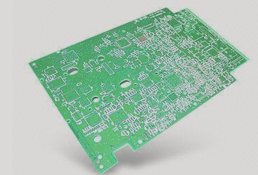
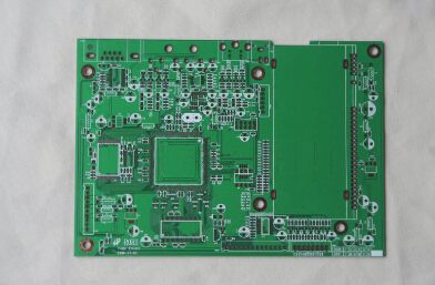
If a circuit board operates in a harsh environment for an extended period, it may encounter various issues that prevent it from functioning properly. When the circuit board fails to operate efficiently, it’s essential to debug it to restore its normal functionality and efficiency. Debugging a circuit board requires specific skills, which I will share below.
**Debugging Skill 1: Measuring Circuit Board Voltage:**
This method begins with using an instrument to verify whether the voltage values at each chip’s power pin on the circuit board fall within the normal range. Additionally, it’s important to check the working voltage at various points to ensure they are also within acceptable limits. For instance, typically, when a silicon transistor is conducting, the base-emitter (BE) junction voltage is around 0.7V, while the collector-emitter (CE) junction voltage is approximately 0.3V or lower. If the BE junction voltage exceeds 0.7V during testing (excluding special transistors like Darlington pairs), it may indicate that the BE junction is open.
**Debugging Method 2: PCB Signal Injection:**

The principle of this method is as follows: connect the signal source to the input terminal, then measure the waveform at each point sequentially to identify any anomalies and locate the fault point. Sometimes, simpler techniques are employed, such as using tweezers to touch the input terminals at various levels to observe the output response. This approach is commonly used in amplification circuits, like those found in audio and video systems. If there is no response at one level but a reaction at the next, it indicates that the issue lies within the previous stage and warrants further inspection.
Debugging Method Three: PCB Debugging Techniques: Observe, Listen, Smell, and Touch.
**Observe:** This involves visually inspecting the circuit board for any obvious mechanical damage, such as deformation or cracking.
**Listen:** Here, the objective is to identify issues by carefully discerning the operational sounds of the circuit board and comparing them to the expected normal sounds.
**Smell:** This entails checking for any burnt odors on the circuit board, such as the scent of capacitor electrolyte. Experienced repair technicians are particularly sensitive to these smells.
**Touch:** This involves physically feeling the components on the circuit board. Ideally, all components should remain within the normal temperature range during operation. Typically, components will heat up when functioning; a lack of heat suggests improper operation. Conversely, overheating in areas that should not be hot is also indicative of a malfunction. For general power transistors and voltage regulator chips, functioning below 70 degrees Celsius is acceptable. Exceeding this threshold can lead to issues.
Effective circuit board adjustment requires specialized instruments for debugging and extensive experience in maintenance. Only through long-term experience can one quickly diagnose and restore a circuit board to its normal operational state.


