
Understanding the PCB Design Process
- PCB design involves two main phases: prototyping and product development.
- Prototyping is crucial for creating hardware that meets specifications.
- The goal of prototyping is to achieve an accurate and efficient product with minimal iterations.
Product Development for PCB Prototypes
- Product development focuses on preparing the PCB for its final application.
- Design specifications like filtering, amplification, and measurement are met during this phase.
- Emphasis is placed on increasing product yield and reducing manufacturing duplication.
Practical Application of Prototype PCB Boards
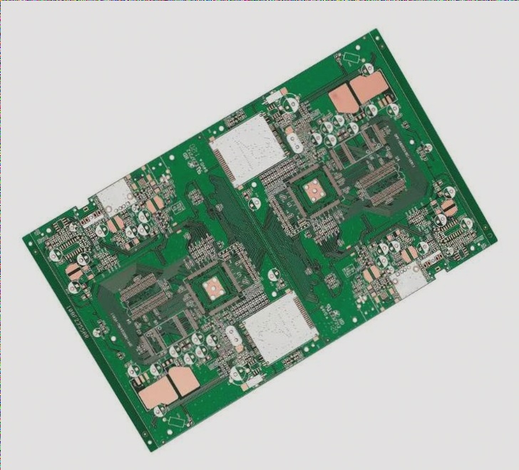
- Prototype PCB boards provide a non-conductive environment for electronic components.
- They offer a cost-effective and efficient alternative to complex wiring methods.
Common Materials Used in PCB Prototypes
- FR-4, a flame retardant epoxy glass cloth laminate, is the most commonly used material for PCBs.
- FR-4 is known for its high resistance to compressive strength and excellent electrical insulation properties.
- It is widely used in manufacturing rigid PCBs and various electronic components.
Components in PCB Prototype Boards
- Electronic components on PCBs are connected to the conductive pattern through soldering.
- Designing PCBs manually can be a time-consuming process, prompting the use of systems to improve efficiency.
- PCB prototype boards facilitate the design of single-layer and multilayer printed boards.
Key Stages in Designing a Printed Circuit Board
- Verifying the created scheme for errors
- Compiling a list of electrical circuit elements
- Placing electronic components on the board
- Creating an electrical circuit diagram
- Automatically tracing a printed circuit board (generating a pattern of printed conductors)
- Generating design documentation
The suggested laboratory work cycle enables students to grasp the primary phases of PCB design.

Exploring the PCB Artist Design Environment
Objective of the task: becoming acquainted with the main components of the software interface
1.1. Overview
CAD PCB Artist comprises two graphic editors: Schematic Design Editor and PCB Design Editor, along with the Library Manager library program and utility tools. A significant portion of the PCB design process
Report Content Requirements
The report should include a step-by-step guide for creating an electrical circuit (with commands) and a printout of the generated schematic file.
Objective of the task: to automatically establish electrical connections on the printed circuit board (performing automatic routing); streamline the layout of printed conductors.
Ensuring Product Quality Measures
To manufacture printed circuit boards in compliance with the International Standard, a quality assurance program must be established and maintained. The ISO 9000 series of quality assurance standards aligns with this International Standard.
Product-specific testing should be conducted to ensure adherence to specifications or as agreed upon by the manufacturer and consumer.
The manufacturer must implement a process control system. The IPC-PC-90 series serves as a system of process control standards.
The manufacturer must have a process control system that meets the stipulations of this standard.
Material Requirements in PCB Prototype Board
All materials utilized in producing printed circuit boards must meet the standards and documentation criteria for their procurement.
Material control should involve certification based on statistical testing of samples to verify that all components in the final product align with the procurement documentation for printed circuit boards.
The manufacturer holds responsibility for meeting all product control requirements outlined in this standard. The user retains the right to conduct any necessary control types listed in this standard to ensure compliance.
The testing, control, and measuring equipment used for testing must be sufficient in quantity, possess the required accuracy and quality, and undergo periodic verification as per the technical regulations for equipment and instruments.
Product Quality Control Regulations
Quality control should be executed using finished printed circuit boards or test coupons.
Product quality for delivery should be verified as per the product specification. The delivery of inspected products should not be delayed due to reliability testing delays.
The specifications for printed circuit boards delivered to the customer should outline the criteria for determining test item type and quantity, as well as the testing frequency.
An inspection lot may be employed for product quality control. The inspection lot should consist of printed circuit boards produced from the same base material, using the same design and manufacturing methods, under identical conditions, within a maximum one-month period, and sent for testing simultaneously.
Testing Prototype PCB Boards
The trace of controlled electrical circuits must be consistent across all printed circuit board control lots. The quality of test boards or special test coupons should be on par with boards produced using the same technology and equipment.
Product acceptance for delivery should be based on successful testing against all requirements specified in the printed circuit board specification.
Importance of Sampling in PCB Inspection
Utilizing sampling in PCB inspection means that any defect found in a sample will represent a flaw in the entire inspection lot. This necessitates adherence to the standards outlined below for handling such situations.
In the event of lot rejection, the manufacturer must remove the defective PCBs and conduct a comprehensive 100% inspection of the batch, as documented by the supplier’s quality control system.
Replacement of defective PCBs must align with the product quality assurance system.
Specifications for Interconnection Lines
The minimum distance between adjacent parallel interconnection lines should be 3.0 mm, with individual UGOs spaced no less than 2.0 mm apart.
All elements depicted on the diagram must be assigned a reference designation, comprising a letter and serial number. Letter designations are essential for certain electrical components.
Simplifying Your Work with Prototype Boards
Prototype boards, despite their simple plastic and metal rail structure, significantly ease work processes. They enable rapid creation of printed circuit prototypes without soldering or etching, saving substantial time and effort in project construction.
Various types of prototype boards are available, such as improvised, fabricated, soldered, or stripboards. However, high-frequency circuits may necessitate specialized boards due to specific component requirements.
While some electronics enthusiasts prefer designing directly on PCBs, even with the potential need for etching repetition in error scenarios, prototype boards remain a popular choice.
Explore Beyond Prototype Boards
Our store not only offers a wide range of prototype boards but also provides accessories, universal boards, and SMD-DIP adapters. We aim to meet all your needs with high-quality products at competitive prices. For any inquiries, our technical department is always ready to assist you.
 العربية
 简体中文
简体中文 Nederlands
 English
 Français
 Deutsch
 Italiano
 日本語
日本語 한국어
한국어 Português
 Русский
 Español
 ไทย
ไทย