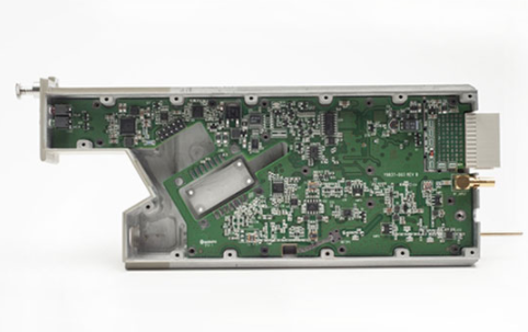
1. How to use the furnace temperature tester
1. Connect the thermometer to the external PCB as per the plug number, and ensure you have gloves and the tester’s thermal insulation box ready.
2. Link the thermometer to the computer using the data cable, and press the “MODE” button lightly to make the “Status” red light blink slowly.

3. Use the left mouse button to click “Connection Change” and “Connection Application” in the tester’s supporting application window to clear the temperature data stored in the tester. Confirm that the thermometer displayed in the “Computer” window shows electricity greater than 60%.
4. Disconnect the thermometer from the computer, place it into the heat insulation box before the reflow oven, press the “MODE” button briefly, and quickly close the heat insulation box when the “Status” red light flashes rapidly. Position the external PCB and heat insulation cover on the steel mesh of the reflow oven, ensuring they are at least ten centimeters apart.
5. After the PCB and heat insulation box exit the reflow oven, promptly open the heat insulation box and press the “MODE” button to make the “Status” red light flash slowly. At this point, the furnace temperature meter should have stopped reading and the furnace temperature data will be stored in its memory.
6. Download the temperature data from the thermometer to the computer, analyze the temperature curve for rationality, print it if possible, and adjust the furnace temperature if necessary.
2. Precautions for using the furnace temperature tester
1. First, check the battery power; if it is below 20%, charge it. Additionally, if the instrument’s surface temperature exceeds 45°C, avoid charging and charge at room temperature.
2. Thermocouple probes are generally small and must be secured at the test position with designated high-temperature solder or adhesive. Failure to do so may result in looseness due to heat, causing deviations and test errors.
3. The heat insulation box can withstand temperatures up to 280°C for a maximum of 9 minutes. Do not exceed this range to ensure the internal temperature of the instrument remains below 85°C.
4. If not used for an extended period, check if the data indicator flashes every 5 seconds. If it does, press and hold the “Start” button for 5 seconds until the indicator flashes abruptly, then observe until the light stops flashing.
5. Ensure the heat insulation box is covered when passing through the furnace; a “click” sound is preferable.
6. Only one furnace temperature tester recorder can be connected to the computer at a time. Connecting multiple recorders to different USB ports simultaneously is not permitted.
7. After completing a furnace cycle, run through the furnace again and use it only after the heat insulation box has cooled down.
The furnace temperature tester monitors the temperature of the PCB board as it enters the furnace and records temperature changes in each zone. Accurate monitoring data results in better welding quality for the PCB board.
1. Connect the thermometer to the external PCB as per the plug number, and ensure you have gloves and the tester’s thermal insulation box ready.
2. Link the thermometer to the computer using the data cable, and press the “MODE” button lightly to make the “Status” red light blink slowly.

3. Use the left mouse button to click “Connection Change” and “Connection Application” in the tester’s supporting application window to clear the temperature data stored in the tester. Confirm that the thermometer displayed in the “Computer” window shows electricity greater than 60%.
4. Disconnect the thermometer from the computer, place it into the heat insulation box before the reflow oven, press the “MODE” button briefly, and quickly close the heat insulation box when the “Status” red light flashes rapidly. Position the external PCB and heat insulation cover on the steel mesh of the reflow oven, ensuring they are at least ten centimeters apart.
5. After the PCB and heat insulation box exit the reflow oven, promptly open the heat insulation box and press the “MODE” button to make the “Status” red light flash slowly. At this point, the furnace temperature meter should have stopped reading and the furnace temperature data will be stored in its memory.
6. Download the temperature data from the thermometer to the computer, analyze the temperature curve for rationality, print it if possible, and adjust the furnace temperature if necessary.
2. Precautions for using the furnace temperature tester
1. First, check the battery power; if it is below 20%, charge it. Additionally, if the instrument’s surface temperature exceeds 45°C, avoid charging and charge at room temperature.
2. Thermocouple probes are generally small and must be secured at the test position with designated high-temperature solder or adhesive. Failure to do so may result in looseness due to heat, causing deviations and test errors.
3. The heat insulation box can withstand temperatures up to 280°C for a maximum of 9 minutes. Do not exceed this range to ensure the internal temperature of the instrument remains below 85°C.
4. If not used for an extended period, check if the data indicator flashes every 5 seconds. If it does, press and hold the “Start” button for 5 seconds until the indicator flashes abruptly, then observe until the light stops flashing.
5. Ensure the heat insulation box is covered when passing through the furnace; a “click” sound is preferable.
6. Only one furnace temperature tester recorder can be connected to the computer at a time. Connecting multiple recorders to different USB ports simultaneously is not permitted.
7. After completing a furnace cycle, run through the furnace again and use it only after the heat insulation box has cooled down.
The furnace temperature tester monitors the temperature of the PCB board as it enters the furnace and records temperature changes in each zone. Accurate monitoring data results in better welding quality for the PCB board.


