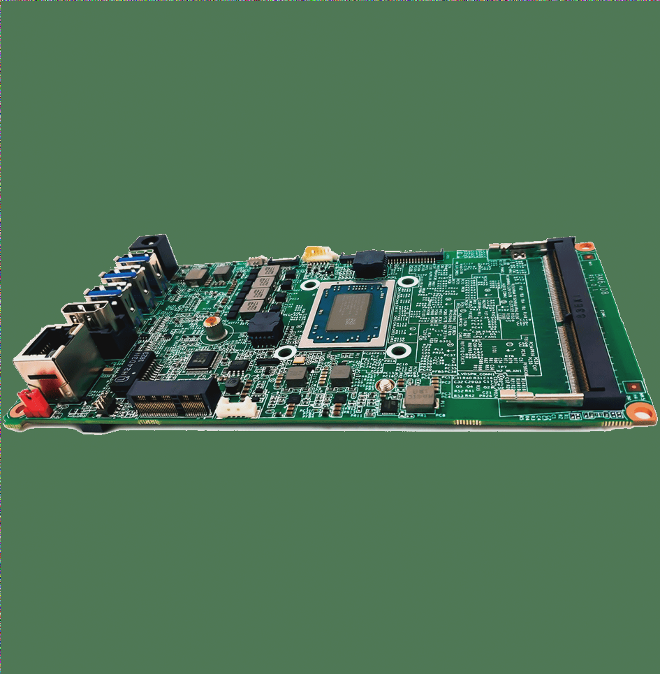
Without proper impedance control, significant signal reflection and distortion can occur, leading to potential design failures. Signals such as PCI, PCI-E, USB, Ethernet, DDR memory, and LVDS require strict impedance control to maintain signal integrity. Achieving this control is primarily accomplished through careful PCB design, which imposes higher demands on the manufacturing process. By collaborating with the PCB manufacturer and utilizing EDA software, designers can adjust trace impedance to meet the specific signal integrity requirements.
The impedance control of a PCB trace can be optimized using different routing methods, each of which has a predictable impact on impedance. The key methods include:
### 1. **Microstrip Line**
A microstrip line consists of a signal trace above a ground plane, with a dielectric material between them. If the dielectric constant, the trace width, and the distance from the ground plane are all carefully controlled, the characteristic impedance can be accurately set. Under these conditions, impedance can be controlled with an accuracy of ±5%, making this method highly reliable for high-speed signals.
### 2. **Stripline**
A stripline is similar to a microstrip, but the signal trace is sandwiched between two ground planes. The control of the trace width, dielectric constant, and the distance between the ground planes is crucial for maintaining consistent impedance. When these factors are controlled, the characteristic impedance can be regulated within 10% accuracy. While not as precise as microstrip lines, striplines offer improved shielding and can be used in more complex designs.
### 3. **Laminate Structure and PCB Parameters**
The manufacturing process and materials used by PCB factories play a crucial role in the final impedance. The thickness of the copper foil used in the surface layer can vary, with common options including 12µm, 18µm, and 35µm, which, after processing, result in final thicknesses of approximately 44µm, 50µm, and 67µm, respectively. Additionally, the core material of the PCB, such as S1141A (a standard FR-4 material), affects overall impedance control. It’s important to coordinate with the PCB manufacturer’s technical support to obtain accurate data on these parameters to ensure the design meets the desired performance standards.
By understanding the specific parameters and using effective impedance control techniques, designers can ensure that signal integrity is maintained throughout the PCB, minimizing the risk of design failures and optimizing performance for high-speed applications.

### 4. Structure of Multilayer PCBs
To achieve proper impedance control in PCB design, understanding the structure of a multilayer board is crucial. Typically, a multilayer PCB consists of several layers, including core boards and prepregs.
**Core Board**: The core board is the fundamental material of the PCB, typically a rigid and thick substrate composed of a copper-clad laminate (often two copper layers). It serves as the backbone of the multilayer stack.
**Prepreg**: Prepreg (pre-impregnated resin) is a bonding material used between layers. It has an initial thickness but will compress during the lamination process, reducing in thickness. Prepreg forms the bonding “wetting layer” between the core board layers.
The outermost layers of a multilayer PCB are typically composed of prepreg layers, and a separate copper foil is applied to the outer surface of the two prepreg layers. The copper foil typically comes in thicknesses such as 0.5 oz, 1 oz, or 2 oz (1 oz ≈ 35 µm or 1.4 mil), with some increase in the thickness of the outer copper foil after surface treatments. The inner copper foil is applied to the core board, and although its original thickness is similar to the outer copper, the thickness decreases slightly due to etching during the PCB manufacturing process.
**Solder Mask**: The outermost layer of a multilayer PCB is usually covered with a solder mask, commonly referred to as “green oil” (although other colors like yellow are also used). The solder mask is typically thinner in areas where there is no copper foil, with the areas around copper being slightly thicker. The thickness of the solder mask varies, but it is often difficult to determine precisely without advanced measuring techniques. It is also noticeable by touch, as the copper areas feel slightly more prominent than the surrounding solder mask.
### 5. Semi-Cured Film and Prepreg Specifications
When selecting materials for a PCB of a given thickness, not only do we need to consider the material properties, but we must also account for the thickness changes that occur during the lamination process. Prepregs are often selected based on specific thicknesses, such as:
– 7628 (0.185mm)
– 2116 (0.105mm)
– 1080 (0.075mm)
– 3313 (0.095mm)
After pressing, the actual thickness of the prepreg is usually 10–15 µm smaller than the original value. In some cases, up to three prepreg layers may be used in a single wetting layer, although each layer’s thickness must be varied. Typically, one prepreg layer is used, but some manufacturers require at least two. If the prepreg thickness is insufficient, copper foils on both sides of the core board may be etched away to make room for thicker prepreg layers.
**Solder Mask Thickness**: The solder mask thickness over copper is typically around 8–10 µm. However, the thickness of the solder mask over areas without copper foil varies based on the copper foil thickness. For example, when the copper thickness is 45 µm, the solder mask thickness (C1) is typically 13–15 µm. For 70 µm copper, the thickness (C1) is usually 17–18 µm.
### Wire Cross Section and Trace Design
The cross-sectional shape of PCB traces is often thought of as a rectangle, but in reality, it is closer to a trapezoid. For example, on the top layer of a PCB with 1 oz copper, the upper base of the trapezoid will be about 1 mil shorter than the lower base. If the line width is 5 mils, the upper base will be approximately 4 mils, and the lower base will be 5 mils. This difference in the upper and lower bases is a result of the copper’s thickness.
**Dielectric Constant**: The dielectric constant of prepreg materials depends on their resin composition and thickness. For common FR4 boards, the dielectric constant typically ranges between 4.2 and 4.7. This value tends to decrease as the frequency increases, which can impact signal integrity at higher frequencies.
**Dielectric Loss Factor**: The dielectric loss factor (tan δ) represents the energy consumed as heat by dielectric materials in the presence of an alternating electric field. For example, S1141A has a typical tan δ value of 0.015. This loss factor is crucial for high-speed designs where signal degradation due to heat can affect performance.
### Differential Pair PCB Trace Requirements
For high-speed designs, differential pair routing is essential for impedance control. Here are key considerations for differential pair routing:
1. **Wiring Mode, Parameters, and Impedance Calculation**: Differential pairs are routed in either microstrip or stripline configurations, depending on whether they are on outer or inner layers. Proper impedance calculation is essential, and tools like POLAR-SI9000 or impedance formulas can help achieve the correct values.
2. **Maintaining Parallel Equidistant Traces**: When routing differential pairs, the traces should be equidistant and parallel. The distance between the traces must remain consistent throughout the design. There are two methods for laying out the traces: side-by-side or over-under. The side-by-side method is preferred, as the over-under method (inter-layer routing) can cause alignment issues during PCB fabrication. Poor alignment between layers and variation in interlayer dielectric thickness can lead to impedance mismatches. Therefore, it’s generally recommended to keep differential pairs on the same layer as much as possible.
By carefully selecting materials, maintaining correct trace spacing, and using the right routing techniques, designers can ensure that the impedance of a multilayer PCB remains stable and optimal for high-frequency performance.
The impedance control of a PCB trace can be optimized using different routing methods, each of which has a predictable impact on impedance. The key methods include:
### 1. **Microstrip Line**
A microstrip line consists of a signal trace above a ground plane, with a dielectric material between them. If the dielectric constant, the trace width, and the distance from the ground plane are all carefully controlled, the characteristic impedance can be accurately set. Under these conditions, impedance can be controlled with an accuracy of ±5%, making this method highly reliable for high-speed signals.
### 2. **Stripline**
A stripline is similar to a microstrip, but the signal trace is sandwiched between two ground planes. The control of the trace width, dielectric constant, and the distance between the ground planes is crucial for maintaining consistent impedance. When these factors are controlled, the characteristic impedance can be regulated within 10% accuracy. While not as precise as microstrip lines, striplines offer improved shielding and can be used in more complex designs.
### 3. **Laminate Structure and PCB Parameters**
The manufacturing process and materials used by PCB factories play a crucial role in the final impedance. The thickness of the copper foil used in the surface layer can vary, with common options including 12µm, 18µm, and 35µm, which, after processing, result in final thicknesses of approximately 44µm, 50µm, and 67µm, respectively. Additionally, the core material of the PCB, such as S1141A (a standard FR-4 material), affects overall impedance control. It’s important to coordinate with the PCB manufacturer’s technical support to obtain accurate data on these parameters to ensure the design meets the desired performance standards.
By understanding the specific parameters and using effective impedance control techniques, designers can ensure that signal integrity is maintained throughout the PCB, minimizing the risk of design failures and optimizing performance for high-speed applications.
### 4. Structure of Multilayer PCBs
To achieve proper impedance control in PCB design, understanding the structure of a multilayer board is crucial. Typically, a multilayer PCB consists of several layers, including core boards and prepregs.
**Core Board**: The core board is the fundamental material of the PCB, typically a rigid and thick substrate composed of a copper-clad laminate (often two copper layers). It serves as the backbone of the multilayer stack.
**Prepreg**: Prepreg (pre-impregnated resin) is a bonding material used between layers. It has an initial thickness but will compress during the lamination process, reducing in thickness. Prepreg forms the bonding “wetting layer” between the core board layers.
The outermost layers of a multilayer PCB are typically composed of prepreg layers, and a separate copper foil is applied to the outer surface of the two prepreg layers. The copper foil typically comes in thicknesses such as 0.5 oz, 1 oz, or 2 oz (1 oz ≈ 35 µm or 1.4 mil), with some increase in the thickness of the outer copper foil after surface treatments. The inner copper foil is applied to the core board, and although its original thickness is similar to the outer copper, the thickness decreases slightly due to etching during the PCB manufacturing process.
**Solder Mask**: The outermost layer of a multilayer PCB is usually covered with a solder mask, commonly referred to as “green oil” (although other colors like yellow are also used). The solder mask is typically thinner in areas where there is no copper foil, with the areas around copper being slightly thicker. The thickness of the solder mask varies, but it is often difficult to determine precisely without advanced measuring techniques. It is also noticeable by touch, as the copper areas feel slightly more prominent than the surrounding solder mask.
### 5. Semi-Cured Film and Prepreg Specifications
When selecting materials for a PCB of a given thickness, not only do we need to consider the material properties, but we must also account for the thickness changes that occur during the lamination process. Prepregs are often selected based on specific thicknesses, such as:
– 7628 (0.185mm)
– 2116 (0.105mm)
– 1080 (0.075mm)
– 3313 (0.095mm)
After pressing, the actual thickness of the prepreg is usually 10–15 µm smaller than the original value. In some cases, up to three prepreg layers may be used in a single wetting layer, although each layer’s thickness must be varied. Typically, one prepreg layer is used, but some manufacturers require at least two. If the prepreg thickness is insufficient, copper foils on both sides of the core board may be etched away to make room for thicker prepreg layers.
**Solder Mask Thickness**: The solder mask thickness over copper is typically around 8–10 µm. However, the thickness of the solder mask over areas without copper foil varies based on the copper foil thickness. For example, when the copper thickness is 45 µm, the solder mask thickness (C1) is typically 13–15 µm. For 70 µm copper, the thickness (C1) is usually 17–18 µm.
### Wire Cross Section and Trace Design
The cross-sectional shape of PCB traces is often thought of as a rectangle, but in reality, it is closer to a trapezoid. For example, on the top layer of a PCB with 1 oz copper, the upper base of the trapezoid will be about 1 mil shorter than the lower base. If the line width is 5 mils, the upper base will be approximately 4 mils, and the lower base will be 5 mils. This difference in the upper and lower bases is a result of the copper’s thickness.
**Dielectric Constant**: The dielectric constant of prepreg materials depends on their resin composition and thickness. For common FR4 boards, the dielectric constant typically ranges between 4.2 and 4.7. This value tends to decrease as the frequency increases, which can impact signal integrity at higher frequencies.
**Dielectric Loss Factor**: The dielectric loss factor (tan δ) represents the energy consumed as heat by dielectric materials in the presence of an alternating electric field. For example, S1141A has a typical tan δ value of 0.015. This loss factor is crucial for high-speed designs where signal degradation due to heat can affect performance.
### Differential Pair PCB Trace Requirements
For high-speed designs, differential pair routing is essential for impedance control. Here are key considerations for differential pair routing:
1. **Wiring Mode, Parameters, and Impedance Calculation**: Differential pairs are routed in either microstrip or stripline configurations, depending on whether they are on outer or inner layers. Proper impedance calculation is essential, and tools like POLAR-SI9000 or impedance formulas can help achieve the correct values.
2. **Maintaining Parallel Equidistant Traces**: When routing differential pairs, the traces should be equidistant and parallel. The distance between the traces must remain consistent throughout the design. There are two methods for laying out the traces: side-by-side or over-under. The side-by-side method is preferred, as the over-under method (inter-layer routing) can cause alignment issues during PCB fabrication. Poor alignment between layers and variation in interlayer dielectric thickness can lead to impedance mismatches. Therefore, it’s generally recommended to keep differential pairs on the same layer as much as possible.
By carefully selecting materials, maintaining correct trace spacing, and using the right routing techniques, designers can ensure that the impedance of a multilayer PCB remains stable and optimal for high-frequency performance.