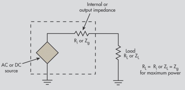
Impedance Matching
Impedance matching refers to the condition where the load impedance is equal to the characteristic impedance of the transmission line. Under this condition, signal reflection is minimized, meaning that all the signal from the source is absorbed by the load. On the other hand, if impedance matching is not achieved, signal loss occurs during transmission. In HDI PCB design, impedance matching plays a crucial role in maintaining signal integrity.
When is Impedance Matching Necessary for PCB Traces?
Impedance matching is not primarily determined by the frequency of the signal but by its steepness—specifically, the rise and fall times. A signal is generally considered high-speed if its rise/fall time (measured from 10% to 90% of the signal) is shorter than 6 times the propagation delay of the trace. For example, a wire delay of 150 ps/inch is commonly assumed in PCB designs.
Characteristic Impedance
The characteristic impedance of a transmission line is the impedance the signal “sees” as it propagates. If the propagation speed is constant along the line and the capacitance per unit length remains uniform, the instantaneous impedance remains consistent throughout the transmission line. This impedance is known as the characteristic impedance, which is influenced by the layer on which the traces are placed, the dielectric constant of the PCB material, trace width, and the gap between the conductor and pad. It is independent of the trace length. In HDI PCB design, the typical impedance for digital signals is 50 ohms, which is an approximation. Coaxial cables typically have a baseband impedance of 50 ohms, a frequency band impedance of 75 ohms, and twisted pair (differential) lines have 100 ohms of impedance.
Common Methods for Impedance Matching
1. Series Termination Matching
When the source impedance is lower than the characteristic impedance of the transmission line, a resistor (R) is placed in series between the signal source and the transmission line. This helps match the output impedance of the source with the characteristic impedance of the line, reducing signal reflections and preventing secondary reflections at the load.
Matching Resistance Selection Principle: The sum of the matching resistor value and the driver output impedance should equal the characteristic impedance of the transmission line. As the output impedance of CMOS and TTL drivers varies with signal levels, achieving a perfect match is difficult; instead, a compromise is used. Signal networks with a chain topology are not suitable for series termination, and all loads should be connected at the end of the transmission line.
Series termination is a widely used method due to its low power consumption, no additional DC load on the driver, and the need for only a resistive component.
Common Applications: Impedance matching for CMOS and TTL circuits, as well as USB signal matching.
2. Parallel Termination Matching
If the signal source impedance is very low, parallel termination is used to match the load impedance to the characteristic impedance of the transmission line. This method eliminates reflections at the load end. It can be implemented with either a single resistor or dual resistors.
Matching Resistance Selection Principle: When the chip’s input impedance is high, the parallel resistance value at the load end should be close to the characteristic impedance of the transmission line in the single-resistor form. For the dual-resistor method, each resistor value should be twice the characteristic impedance of the transmission line.
The main advantages of parallel termination matching are its simplicity and ease of implementation. However, it introduces DC power consumption. The single-resistor method’s power consumption depends on the signal duty cycle, while the dual-resistor method dissipates DC power regardless of the signal level, but the current is halved compared to the single-resistor method.
Common Applications: High-speed signal applications, including:
- SSTL drivers (e.g., DDR, DDR2) use a single resistor in parallel with VTT (typically half of IOVDD). The DDR2 data signal’s parallel matching resistor is often built into the chip.
- High-speed serial data interfaces, such as TMDS, which use a single resistor in parallel with IOVDD at the receiving device, with a 50-ohm single-ended impedance (100 ohms for differential pairs).
If you have any questions about PCB or PCBA, feel free to contact us at info@wellcircuits.com.