PCB Board Impedance: Understanding and Control
PCB board impedance management is crucial for maintaining signal integrity in high-frequency circuits. By controlling impedance, designers ensure consistent signal transmission and prevent distortion. Achieving uniform impedance across the system is essential for proper impedance matching throughout the PCB design.
Factors Impacting Impedance in PCB Design
- Line Width (W) / Line-to-Line Distance: The width of PCB traces and spacing between them affect impedance. Increasing line width reduces impedance, while increased line-to-line distance raises impedance, crucial for high-speed signals.
- Insulation Thickness (H): Thicker insulation layers increase impedance by reducing signal propagation ability.
- Copper Thickness (T): Thicker copper traces lower impedance due to lower resistance, improving signal transmission.
- Solder Mask Thickness (H1): Thicker solder mask decreases impedance by affecting field distribution around traces.
- Dielectric Constant (Er): Higher dielectric constants decrease impedance by reducing signal propagation speed.
- Undercut (W1 – W): Increasing undercut width raises impedance by altering trace geometry.
Additional Considerations: Solder Mask and Dielectric Impact
The solder mask indirectly affects impedance by increasing the dielectric constant, reducing impedance by approximately 4% and enhancing signal integrity.
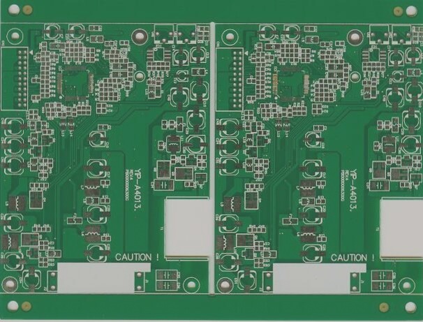
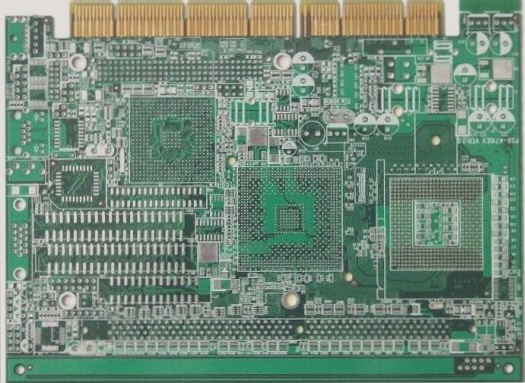
PCB Material Composition
PCBs are primarily made of copper-clad laminate, comprising a substrate, copper foil, and adhesive. The substrate provides structural integrity, while copper foil facilitates electrical connections between components.
Overview of PCB Board Materials
Copper-clad laminates typically range from 35 to 50 µm in thickness. Single-sided laminates have copper foil on one side, while double-sided laminates feature copper foil on both sides, adhered by an adhesive layer. Common thickness options include 1.0mm, 1.5mm, and 2.0mm.
Types of Copper-Clad Laminates
Copper-clad laminates vary based on insulating materials, binder resins, and applications. Types include general-purpose and specialized variants, such as Copper-Clad Phenolic Paper Laminate.
Laminates Used in Printed Circuit Boards (PCBs)
This laminate is made of insulating paper, typically impregnated with phenolic resin and hot-pressed to create the final product. The paper used can be TFz-62 (insulating impregnated paper) or 1TZ-63 (cotton fiber impregnated paper). One side of the laminate may be strengthened with a single sheet of alkali-free glass impregnated cloth. This type of laminate is widely utilized in PCBs for radio equipment.
Copper-Clad Phenolic Glass Cloth Laminate
Created by impregnating alkali-free glass cloth with a phenolic epoxy resin and hot-pressing it, this laminate has copper foil applied to one or both sides. It is prized for its lightweight nature, outstanding electrical and mechanical properties, and ease of processing. The surface usually appears light yellow, but when melamine is used as the curing agent, it turns light green with improved transparency. This laminate is employed in PCBs requiring higher operating temperatures and frequencies, such as those in radio and communication equipment.
Copper-Clad PTFE Laminate
This laminate comprises a PTFE (Polytetrafluoroethylene) substrate coated with copper foil through hot pressing. PTFE is recognized for its high dielectric strength, making it ideal for high-frequency and ultra-high-frequency applications. Copper-clad PTFE laminates are commonly found in RF (radio frequency) circuits and high-performance communication systems.
Copper-Clad Epoxy Glass Cloth Laminate
A commonly used material for hole-metallized printed circuit boards, this laminate combines epoxy resin with glass cloth for the substrate. It is highly durable and possesses good electrical properties, making it suitable for most general PCB applications, including those requiring metalized holes for through-hole connections.
Flexible Polyester Copper-Clad Film
This material, shaped like a ribbon, is produced by hot-pressing polyester film with copper. It is flexible and frequently employed in applications where the PCB needs to be bent or shaped to specific forms, such as flexible printed circuits (FPCs) and printed cables. This material is commonly used as a transition line in connectors or in devices requiring flexibility and resistance against moisture. Epoxy resin encapsulation is often applied for additional durability and protection.
Substrate Types in Copper-Clad Laminates
- Paper Substrates: Typically used for cost-effective applications with basic mechanical requirements.
- Glass Fiber Cloth Substrates: Known for superior mechanical strength and electrical performance, commonly used in high-end PCBs.
- Synthetic Fiber Cloth Substrates: Less common but used in applications needing specific mechanical properties.
- Non-Woven Fabric Substrates: Utilized in specialized applications, offering flexibility and increased strength.
- Composite Substrates: These substrates blend different materials to achieve desired mechanical and electrical properties.
Conclusion
Copper-clad laminates play a crucial role in PCB manufacturing, with the selection dependent on the specific electrical, mechanical, and environmental demands of the application. From basic phenolic paper laminates to high-frequency PTFE boards, these materials provide a wide array of choices for various industries like communications, automotive, and consumer electronics. As technology progresses, the continuous development of new and enhanced CCL materials will steer innovation in PCB design and production.