Infrared (IR) remote controllers are ubiquitous, controlling most of the appliances we use daily. In this article/video, we will guide you through building a versatile device that can decode signals from almost any IR remote control. This device allows you to use your existing remote control to switch relays (and consequently, various loads), enabling applications like controlling lights, curtains, or other appliances without needing to purchase new remotes or expensive hardware. The core of this project is the ATTiny85 microcontroller. The device can store up to three IR codes in its EEPROM memory and switch three separate devices. Each relay can handle up to 10A of current. The load switching logic (momentary ON/OFF, toggling, etc.) can be customized according to your needs.
The schematic and PCB design were created using Altium Designer 21.4.1, alongside the SamacSys component libraries (via the SamacSys Altium Plugin). For IR signal analysis, I utilized the Siglent SDS2102X Plus oscilloscope.
The device performs reliably, reacting promptly to transmitted IR signals. Let’s dive into the details of building this project!
A. Circuit Analysis
Figure 1 presents the schematic of the IR remote control decoder/switcher. As you can see, both decoding and switching functionalities are handled by a single 8-pin ATTiny85 microcontroller.
Figure 1
Schematic of the infrared remote control decoder/switcher board
REG1 is the well-known 7805 through-hole voltage regulator [1], providing a stable +5V supply for the relays. Capacitors C4 and C5 filter out noise, while FB1 and C11 block input noise spikes. IC2 is the TS2937CW-5.0 regulator [2], which ensures a clean +5V supply for the microcontroller (U1) and other components. D8 indicates proper supply voltage, and capacitors C8 and C9 reduce output noise.
U1 is the VS1838 infrared receiver module [3]. Given its sensitivity to supply noise, R7 and C6 form a low-pass filter to reduce power supply interference. The output from U1 connects to the PB3 pin of IC1 and to the gate of the Q4 MOSFET.
Q1 is a FDN360P P-Channel MOSFET [4], used to supply power to the D7 LED, which indicates when IR signals are successfully received. R8 limits the current to D7. SW1 is a tactile pushbutton, while C10 helps debounce the mechanical switch action.
IC1, the ATTiny85 microcontroller [5], is a compact, versatile chip offering 8K flash memory and capable of running up to 20 MHz with an external crystal. For this project, the internal 8 MHz clock is used. Capacitor C7 filters out supply noise to ensure stable operation.
Q1, Q2, and Q3 are SI2303 N-Channel MOSFETs [6], which drive relays K1, K2, and K3. Resistors R4, R5, and R6 pull the gate pins of the MOSFETs to ground when inactive, while diodes D1, D2, and D3 protect the MOSFETs from inductive voltage spikes when the relays switch. D4, D5, and D6 serve as indicators for relay activation, and capacitors C1, C2, and C3 help filter noise from the relay coils.
The ISP header is a 5-pin male header used for programming the ATTiny85 using an AVR-ISP programmer. P1, P2, and P3 are 2-pin Phoenix connectors for external device connections.
B. PCB Layout
Figure 2 shows the PCB layout of the IR remote control switcher. It is a two-layer PCB with most components in surface-mount package types for compactness and ease of assembly.

Figure 2
PCB layout of the infrared remote control switcher board
The schematic and PCB designs were created using Altium Designer [7], a powerful and user-friendly tool for electronics design. For components without predefined libraries, I used the free and IPC-compliant SamacSys component libraries. These libraries were easily imported into the Altium project using the SamacSys Altium Plugin [8]. SamacSys supports a wide range of electronic design CAD software, as shown in Figure 3.

Figure 3
Supported CAD software for SamacSys plugins
For the components IC1 [9], IC2 [10], REG1 [11], Q1-Q3 [12], and Q4 [13], I used the SamacSys libraries. Alternatively, you can manually download component libraries from componentsearchengine.com. Figure 4 shows the components selected via the SamacSys Altium plugin.

Figure 4
Selected components in the SamacSys Altium plugin
C. Assembly and Testing
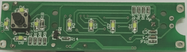
Figure 5 shows the assembled PCB board. The PCBs were fabricated by Wellcircuits, and I am pleased with the quality—assembly was smooth, and I had no issues soldering the components. I highly recommend investing in quality PCBs rather than opting for cheap alternatives.

Figure 5
Assembled PCB of the infrared remote control switcher
C-1. Code
The code was written using the Arduino IDE, but you don’t need an Arduino board. You can install the custom ATTiny board manager and export the compiled HEX file. Program your ATTiny85 using an AVR-ISP programmer or similar tools. The bootloader is not required.