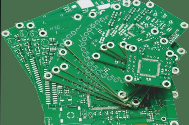
(1) The printed circuit should not have any cross circuits. To address possible cross lines, two methods can be used: drilling and winding. This means that a lead can be “drilled” from the gap at the foot of other resistors, capacitors, transistors to avoid crossing, or a lead can be “wound around” from one end to the other to prevent crossing. In complex cases, where the circuit is very complicated, wire crossovers can also be used to solve cross circuit issues.
(2) Resistors, diodes, tubular capacitors, and other components can be installed in two ways: “vertical” or “horizontal”. Vertical installation means the assembly body is installed perpendicular to the circuit board, saving space, while horizontal installation means the assembly body is installed parallel and close to the circuit board, providing better mechanical strength. The hole spacing for these two different mounting orientations on the printed circuit board varies.
(3) The connection points of circuits at the same level should be as close as possible, and the power filter capacitor of each level circuit should also be connected to the same level connection point. For example, the transistor base and emitter connection points should not be too far apart to prevent interference and self-excitation. By using the “point grounding method” in the circuit, stability is improved and self-excitation is reduced.
(4) The total ground wire must follow the principle of high frequency – medium frequency – low frequency in a hierarchical order from weak to strong electrical signals. Ground wires should not be connected haphazardly, and lengths between levels can be extended as needed, but the hierarchical order must be maintained. Grounding arrangements for components like frequency conversion heads, regeneration heads, and frequency modulation heads must be strict to prevent self-excitation and ensure proper functioning. Large area surrounding ground wires are often used in frequency modulation circuits for better shielding.
(5) Strong current leads such as common ground leads and power amplifier leads should be as wide as possible to reduce wiring resistance and voltage drop, thus minimizing parasitic coupling and self-excitation.
(6) High impedance wiring should be kept as short as possible to prevent whistling and signal absorption, which can lead to circuit instability. Power lines, ground lines, non-feedback component baselines, and emitter leads are examples of low impedance wiring. It is important to separate the baseline of the emitter follower and the ground lines of the two sound channels of the recorder until they are reunited at the end of their function to prevent crosstalk and maintain separation for optimal performance.


