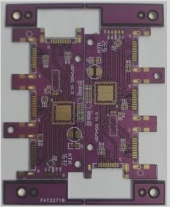
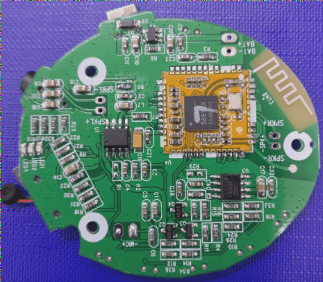
Modern solder paste printers typically include plate loading, solder paste application, imprinting, and circuit board transfer. The working principle involves first securing the circuit board onto the printing positioning table. Next, solder paste or adhesive is applied onto the designated pads via the printer’s left and right scrapers using a stencil. Finally, the board is transferred to the placement machine for automatic component placement.
2. Mounter
The mounting machine, also referred to as a “pick-and-place machine” or “Surface Mount System,” is positioned in the production line after the solder paste printer. It operates by moving the placement head to accurately position surface-mounted components onto the PCB pads. These machines are available in both manual and automatic versions.
3. Reflow Soldering

1. Within the reflow soldering process, there is a heating circuit that heats air or nitrogen to sufficiently high temperatures, directing it towards the circuit board where components are attached. This action melts the solder on both sides of the component, securely bonding it to the motherboard. The benefits of this method include easy temperature control, prevention of oxidation during the soldering process, and more manageable manufacturing costs.
2. **AOI Detector**
The full term for AOI (Automatic Optical Inspection) is automatic optical inspection, which utilizes optical principles to identify common defects encountered during soldering production. AOI is an emerging test technology that is rapidly advancing, with many manufacturers adopting AOI testing equipment. In the automatic inspection process, the machine scans the PCB using a camera, capturing images to compare the tested solder joints against qualified parameters in the database. After image processing, defects on the PCB are identified and displayed or marked for repair by maintenance personnel.
3. **Component Trimming Machine**
This machine is used to cut and shape pin components.
4. **Wave Soldering**
Wave soldering involves making the soldering surface of the plug-in board come into direct contact with high-temperature liquid tin to achieve soldering. The liquid tin is maintained at an angle, and a specialized device creates a wave-like motion in the tin, hence the term “wave soldering.” The primary material used in this process is solder bars.
5. **Tin Furnace**
Generally, the tin furnace refers to a welding tool used in electronic soldering. For discrete component circuit boards, it offers consistent welding results, convenient operation, speed, and high efficiency, making it a valuable asset in production and processing.
6. **Plate Washer**
This equipment is used to clean the PCBA board, effectively removing residue left after soldering.
7. **ICT Test Fixture**
ICT testing primarily involves probes contacting the test points on the PCB layout to detect issues such as open circuits, short circuits, and the soldering condition of all components on the PCBA.
8. **FCT Test Fixture**
FCT (Functional Test) refers to creating a simulated operating environment (including stimulus and load) for the test target board (UUT: Unit Under Test). This allows the board to operate in various design states to gather parameters that verify the functionality of the UUT. In simple terms, it involves applying appropriate stimuli to the UUT and measuring whether the output responses meet the required standards.
9. **Aging Test Frame**
The burn-in test rack allows for batch testing of PCBA boards, simulating long-term user operations to identify problematic boards.


 العربية
 简体中文
简体中文 Nederlands
 English
 Français
 Deutsch
 Italiano
 日本語
日本語 한국어
한국어 Português
 Русский
 Español
 ไทย
ไทย