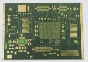
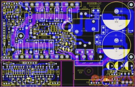
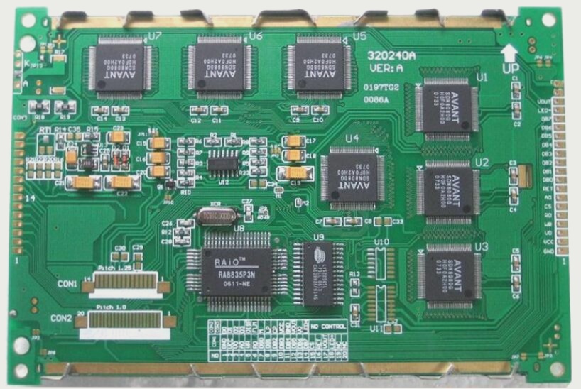
1. The role of PCB passive components in the electronics industry parallels that of integrated circuits (ICs). They are situated upstream and are vital components within electronic products. Electronic circuits consist of both active and passive devices. Passive components can function independently of an electrical connection, serving purposes such as regulating current and voltage, storing static electricity, preventing electromagnetic interference, and filtering current impurities.
2. In contrast to active components, the resistance and impedance of passive components remain constant, even when voltage changes.
3. Passive components encompass three main categories: resistors, inductors, and capacitors.
4. Traditionally, electromagnetic compatibility (EMC) has been perceived as “black magic.” However, EMC can be demystified using mathematical formulas. Despite the availability of these mathematical analysis methods, the equations can be overly complex for practical EMC circuit design. Fortunately, engineers often do not need to fully grasp these intricate mathematical concepts and the theoretical frameworks outlined in EMC specifications. By utilizing straightforward mathematical models, they can effectively understand how to meet EMC requirements.
5. This article employs simple mathematical formulas and electromagnetic theory to elucidate the hidden behaviors and characteristics of passive components on printed circuit boards (PCBs). Understanding these aspects is essential for engineers aiming to design electronic products that comply with EMC standards. Basic knowledge in this area is imperative.
1. **Wire and PCB Trace**
The often-overlooked components such as wires, traces, and mounting frames can serve as significant transmitters of radio frequency energy, effectively acting as sources of electromagnetic interference (EMI). Every component possesses some inductance, including the bond wires of silicon chips and the leads of resistors, capacitors, and inductors. Each wire or trace carries inherent parasitic capacitance and inductance. These parasitic elements influence the wire’s impedance and are particularly sensitive to frequency. Depending on the value of LC (which determines the self-resonance frequency) and the length of the PCB trace, self-resonance can occur between a component and the PCB trace, effectively creating a highly efficient radiating antenna.
At low frequencies, wires primarily exhibit resistive characteristics. However, at high frequencies, their behavior is dominated by inductance. As frequency increases, impedance changes, impacting the electromagnetic compatibility (EMC) design between the wire or PCB trace and the ground. At this stage, employing a ground plane and ground grid becomes essential.
The primary distinction between wires and PCB traces lies in their shapes: wires are typically round, while traces are rectangular. The impedance of a wire or trace encompasses resistance ( R ) and inductive reactance ( X_L = 2pi f L ). At high frequencies, this impedance can be expressed as ( Z = R + jX_L ) with no capacitive reactance ( X_C = frac{1}{2pi f C} ). When the frequency exceeds 100 kHz, inductance surpasses resistance. At this point, the wire or trace transitions from being a low-resistance connection to functioning as an inductive component. Generally, wires or traces operating above audio frequencies should be treated as inductors and can effectively act as radio frequency antennas.
Most antennas are designed to be 1/4 or 1/2 the wavelength (( lambda )) of a specific frequency. Therefore, EMC specifications restrict wires or traces from operating below ( lambda/20 ) of a particular frequency, as this would inadvertently transform them into high-performance antennas. Inductance and capacitance can induce circuit resonance, a phenomenon not typically reflected in specifications.
For instance, consider a 10 cm trace with ( R = 57 , mOmega ) and ( 8 , nH/cm ), resulting in a total inductance of 80 nH. At 100 kHz, this yields an inductive reactance of 50 mΩ. When the frequency surpasses 100 kHz, this trace behaves predominantly as an inductor, with its resistance becoming negligible. Consequently, at frequencies above 150 MHz, this 10 cm trace can act as an effective radiating antenna. At 150 MHz, ( lambda ) equals 2 meters, leading to ( lambda/20 = 10 , cm ), which corresponds to the trace length; frequencies exceeding 150 MHz will further reduce ( lambda ), with ( 1/4lambda ) or ( 1/2lambda ) values nearing the trace length (10 cm), gradually shaping it into a perfect antenna.
2. **Resistance**
Resistors are among the most common components found on PCBs. The material of the resistor—whether carbon composite, carbon film, mica, or wire-wound—affects frequency response and EMC performance. Wire-wound resistors are generally unsuitable for high-frequency applications due to their significant inductance. While carbon film resistors do have some inductance, their lower pin inductance sometimes makes them acceptable for high-frequency use.
3. **PCB Capacitance**
Capacitors are primarily used in power buses to provide decoupling, bypassing, and maintaining stable DC voltage and current (bulk) functions. A truly ideal capacitor retains its capacitance until reaching the self-resonant frequency. Beyond this frequency, its characteristics shift, resembling those of an inductor. This is described by the formula: ( X_C = frac{1}{2pi f C} ), where ( X_C ) represents capacitive reactance (measured in ohms). For example, a 10μF electrolytic capacitor has a capacitive reactance of 1.6Ω at 10 kHz, dropping to 160μΩ at 100 MHz. Thus, at 100 MHz, it behaves almost like a short circuit, making it ideal for EMC applications. However, parameters like equivalent series inductance (ESL) and equivalent series resistance (ESR) can limit electrolytic capacitors to effective operation only below 1 MHz.
The performance of PCB capacitors is also influenced by pin inductance and physical structure, which determine the quantity and size of parasitic inductances. These parasitic inductances arise between the capacitor’s solder joints and can cause the capacitor to behave inductively when exceeding its self-resonance frequency, leading to a loss of its intended function.

