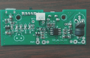
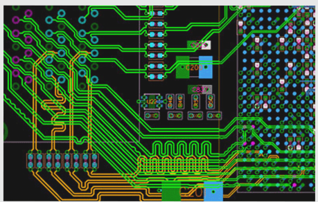
It is essential to focus on certain details during PCB board inspection to enhance our preparedness in ensuring product quality. When examining PCB boards, we should keep in mind the following nine guidelines.
1. It is strictly prohibited to use grounded test equipment to contact live TV, audio, video, and other devices on the base plate for testing the PCB board without an isolation transformer.
2. Directly testing TV, audio, video, and other devices without a power isolation transformer using instruments and equipment with grounded enclosures is strictly forbidden. While general radio cassette recorders typically have a power transformer, it is crucial to determine whether the chassis of more specialized TV or audio equipment is energized, particularly when dealing with output power or the type of power supply used. Failing to do so may easily lead to the backplane of the TV, audio, and other equipment becoming charged, resulting in a power supply short circuit that can damage the integrated circuit and exacerbate existing faults.
—
Let me know if you need further adjustments!

1. Pay attention to the insulation performance of the electric soldering iron when working with the PCB board.
2. It is prohibited to use a powered soldering iron for soldering; ensure the soldering iron is not live. Ideally, ground the shell of the soldering iron. Exercise caution, especially with MOS circuits. Utilizing a low voltage soldering iron of 6–8V is safer.
3. Before testing the PCB board, familiarize yourself with the working principles of integrated circuits and related circuits.
4. Prior to inspecting and repairing an integrated circuit, you should understand its function, internal circuitry, key electrical parameters, the role of each pin, the normal voltage at each pin, the waveform, and the operational principles of the surrounding components. Meeting these criteria will significantly ease analysis and inspection.
5. Avoid creating short circuits between pins when testing the PCB board.
6. When measuring voltage or testing waveforms with an oscilloscope probe, ensure no short circuits occur between the integrated circuit pins due to lead or probe slippage. It’s best to measure directly on the peripheral printed circuit connected to the pins. Even brief short circuits can easily damage the integrated circuit, so exercise extra caution with flat-package CMOS integrated circuits.
7. The internal resistance of the PCB testing instrument should be high.
8. When measuring DC voltage at IC pins, use a multimeter with a head resistance greater than 20KΩ/V; otherwise, significant measurement errors may occur on certain pins.
9. Be mindful of heat dissipation in power integrated circuits during PCB detection.
10. Power integrated circuits must have effective heat dissipation; they should not operate in high-power states without a heat sink.
11. Reasonably handle the detection of PCB board leads.
12. When replacing damaged integrated circuit components with external ones, choose small components and ensure the wiring is sound to prevent unnecessary parasitic coupling, particularly between the audio power amplifier and preamplifier circuits.
13. Ensure the quality of PCB soldering when detecting boards.
14. The PCB must be securely soldered, as solder accumulation and voids can lead to false soldering. Soldering should not exceed 3 seconds, and the soldering iron’s power should be around 25W with internal heating. After soldering an integrated circuit, verify with an ohmmeter that there are no shorts between the pins and ensure no solder bridging before applying power.
15. Avoid hastily concluding that an integrated circuit is damaged while inspecting the PCB board.
16. Do not prematurely determine that an integrated circuit is defective. Many integrated circuits are directly coupled, and abnormal circuit behavior can cause multiple voltage changes, not necessarily indicating IC damage. Moreover, even if the measured pin voltages differ from the expected values, it doesn’t always imply the integrated circuit is functioning correctly, as some soft faults may not affect DC voltage readings.


