The packaging density of multilayer PCB boards is increasing rapidly. Therefore, even for low densities, automated detection is essential and cost-effective. In the complex detection of multilayer PCB boards, two standard methods are needle-bed and flying-probe tests.
1. Needle-Bed Test Method
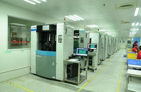
This method connects a spring-loaded probe to each detection point on a multilayer PCB board. Springs apply a pressure of 100-200g to ensure good contact, and these probes are grouped together in “needle beds”. Controlled by detection software, detection points and signals can be programmed. Figure 14-3 illustrates a typical needle-bed tester structure capable of obtaining information from all test points. Only probes necessary for testing are installed. Although needle-bed testing can be performed simultaneously on both sides of a multilayer PCB board, during multilayer PCB board design, all points should be on the soldered side. Needle-bed testers are costly and require meticulous maintenance. Different arrays of probes are selected based on specific applications.
A primary standard probe array consists of a drilled plate with 100, 75, or 50 mil pin center spacing. Each pin acts as a probe, establishing direct mechanical connections via electrical nodes or connectors on the multilayer PCB board. If bonding pads on the multilayer PCB board align with the test array, a polyvinyl film punched to specifications is placed between the array and the board to aid in specific detection designs. Continuity detection occurs by accessing the endpoint of the array, defined by the X-Y coordinates of the pad. This ensures continuous detection of each network on the multilayer PCB board. However, the proximity of the probe limits the effectiveness of needle-bed testing.
Flying Test
2. Dual Probe or Flying Test
The flying needle tester operates independently of the pin configuration fixed on the fixture or bracket. In this system, two or more probes are attached to a small, freely movable magnetic head in the X-Y plane, and testing points are defined directly using CADI Gerber data. These dual probes can move within a 4 mil proximity to each other, offering flexibility in positioning without physical restrictions. The tester with two movable arms measures capacitance by tightly pressing the multilayer PCB against an insulating layer on a metal plate, mimicking the behavior of a capacitor. Increased capacitance indicates potential shorts between lines, while reduced capacitance suggests breaks.
Testing speed significantly influences tester selection criteria. A needle-bed tester can efficiently test thousands of points simultaneously, whereas a flying needle tester is limited to testing only two or four points at a time. Moreover, a needle-bed tester may take as little as 20 to 30 seconds for single-sided testing, depending on board complexity, whereas a flying needle tester may require an hour or more for similar evaluations. Shipley (1991) notes that despite its slower speed, flying needle testing technology remains advantageous for manufacturers dealing with complex, lower-volume multilayer PCB production.
For bare panel testing, specialized instruments (Lea, 1990) are available. Alternatively, a cost-effective approach involves using a versatile instrument initially more expensive than dedicated counterparts but offsetting costs with reduced setup expenses. Standard rasters for panel and surface-mount devices with pin components typically feature a 2.5mm pitch, necessitating test pads of at least 1.3mm. For smaller Imm rasters, test pads should exceed 0.7mm to avoid damage. Crum (1994b) underscores that combining a universal tester (standard raster tester) with a flying tester ensures precise and economical testing of high-density multilayer PCBs. He also advocates for the use of a conductive rubber tester to detect non-standard pad heights caused by hot air leveling, which can complicate test point connections.
Detection methods generally span three tiers:
1) Bare panel detection;
2) In-line detection;
3) Functional testing.
Universal testers are adept at handling a variety of styles and applications for multilayer PCBs, making them suitable for both standard and specialized testing requirements.