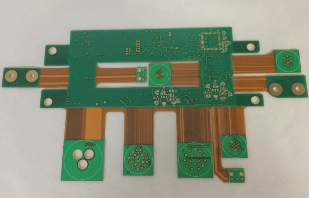
FPCB, also known as flexible printed circuit board, is also referred to as a soft board. Compared to hard, non-flexible PCBs or HDIs, FPCB exhibits distinct differences in material characteristics. It has become crucial in the design of electronic products today. Commonly, a blend of soft and hard materials is used, and this article will delve into the soft characteristics of the soft board, discussing its materials, manufacturing processes, and key components, and explaining the limitations of its use.
**FPCB Material Characteristics**
The product features of FPCB include not only its flexibility but also its lightweight and thin structure. The material can be bent numerous times without damaging the insulating layer, unlike hard PCBs. However, the flexible plastic substrate and wire layout of FPCB make it unsuitable for high conduction currents and voltages. Consequently, FPCB is rarely used in high-power electronic circuits. It is, however, widely used in electronic products with lower power consumption.
Due to the high cost of key materials like PI, FPCB’s unit cost remains elevated. Therefore, it is typically not used as the primary carrier board in product designs. Instead, FPCB is applied in areas where “soft” characteristics are essential. For example, FPCB is used in the electronic zoom lenses of digital cameras or in the optical drive read head circuits, where the need for movement and flexibility outweighs the limitations of traditional rigid circuit board materials.

1. It was initially used in aerospace and military applications in its early days, and now it excels in consumer electronics.
2. In the 1960s, the use of flexible printed circuits (FPCs) was quite common. At that time, the unit price of finished FPCs was high. Although they were lightweight, flexible, and thin, the cost remained high. They were predominantly employed for high-tech, aerospace, and military applications. By the late 1990s, FPCs began to see widespread use in consumer electronics. Around 2000, the United States and Japan were the primary producers of FPCs due to their control over FPC materials. This dominance contributed to the high cost of flexible circuit boards.
3. PI, also known as polyimide, is notable for its heat resistance and molecular structure. Among polyimides, there are different types such as fully aromatic PI and semi-aromatic PI. Fully aromatic PI is linear and consists of infusible, thermoplastic substances. Infusible materials cannot be injection molded during production but can be compressed and sintered, whereas thermoplastic materials can be produced by injection molding.
4. Semi-aromatic PI, including Polyetherimide, is typically thermoplastic and can be manufactured by injection molding. Thermosetting PI, on the other hand, can be laminated, compressed, or transferred for molding depending on the characteristics of the raw materials.
5. FPCB board materials are known for their high heat resistance and stability. For final products made from chemical materials, PI can be used for gaskets and sealing materials, while bismaleimide materials serve as the base for flexible multilayer circuit boards. Among polymer materials, fully aromatic PI offers the highest heat resistance, with temperatures reaching up to 250–360°C. Bismaleimide PI, used for flexible circuit boards, has slightly lower heat resistance, generally around 200°C.
6. Bismaleimide PI has excellent mechanical properties, with minimal temperature variations and high stability in elevated temperature environments. It exhibits low creep deformation and low thermal expansion rates, remaining stable within the temperature range of -200 to +250°C. Additionally, bismaleimide PI shows outstanding chemical resistance. When immersed in 5% hydrochloric acid at 99°C, it maintains a significant level of tensile strength. It also has excellent friction and wear resistance, suitable for applications prone to wear.
7. Besides material characteristics, the structure of the FPCB substrate is crucial. The FPCB consists of a cover film (upper layer) for insulation and protection, along with an insulating base material, rolled copper foil, and adhesive. Common substrate materials for FPCB include polyester (PET) and polyimide (PI), each with distinct advantages and disadvantages.
8. FPCB production materials and procedures enhance the flexibility of terminals. FPCBs are used in wiring, printed circuits, connectors, and multifunctional integrated systems. They can be designed for space efficiency, shape alterations, folding, and flexural design. Additionally, FPCB design helps mitigate electrostatic interference. Flexible circuit boards can reduce overall product volume and design complexity if cost is not a concern.
9. The structure of an FPCB is relatively simple, comprising an upper protective layer and a middle wire layer. During mass production, soft circuit boards are matched with positioning holes for alignment and post-processing. The board’s shape can be altered as needed, or it can be used in a folded form. High-efficiency EMI issues are addressed with anti-EMI and static-resistant insulation designs on the outer layer.
10. On the key circuits of the board, the top layer of the FPCB is copper, which may include RA (Rolled Annealed Copper) or ED (Electro Deposited) copper. ED copper is cost-effective but prone to fractures, while RA copper, though more expensive, offers better flexibility. Consequently, high-deflection flexible circuit boards predominantly use RA materials.
11. For FPCB formation, layers of cover film, calendered copper, and base material are bonded with adhesives. Common adhesives include acrylic and epoxy. Epoxy resin, with lower heat resistance, is typically used for household items, while acrylic offers high heat resistance and bonding strength but has poorer insulation and electrical properties. In FPCB manufacturing, adhesive thickness ranges from 20 to 40 μm of the overall thickness.
12. For highly flexible applications, reinforcement and integrated design improve material performance. In the FPCB manufacturing process, copper foil and substrate are prepared, followed by cutting, perforation, and electroplating. After completing the FPCB holes, the photoresist material coating is applied, followed by exposure and development. Solvent etching forms the conductive circuit, and the surface is cleaned. Adhesive is applied to the base layer and etched copper foil, and the cover layer is attached.
13. After these steps, the FPCB is about 80% complete. Further processing includes adding connection points, such as guide welding openings, and appearance processing like laser cutting. If the FPCB is a soft and hard composite board or requires welding with a functional module, secondary processing or reinforcement board design is performed.
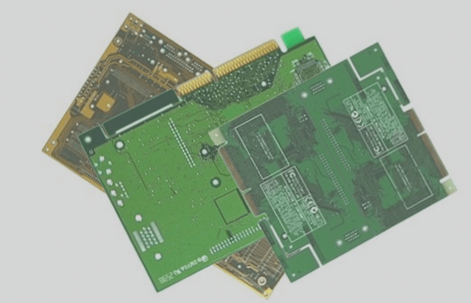
14. FPCB offers various applications and is relatively easy to manufacture. However, FPCB alone cannot accommodate overly complex and compact circuits due to the risk of copper foil fractures with excessive flexing. For intricate circuits, core HDI high-density multilayer boards are used to meet complex circuit requirements and support numerous data transmission interfaces or I/O connections.
**FPCB Material Characteristics**
The product features of FPCB include not only its flexibility but also its lightweight and thin structure. The material can be bent numerous times without damaging the insulating layer, unlike hard PCBs. However, the flexible plastic substrate and wire layout of FPCB make it unsuitable for high conduction currents and voltages. Consequently, FPCB is rarely used in high-power electronic circuits. It is, however, widely used in electronic products with lower power consumption.
Due to the high cost of key materials like PI, FPCB’s unit cost remains elevated. Therefore, it is typically not used as the primary carrier board in product designs. Instead, FPCB is applied in areas where “soft” characteristics are essential. For example, FPCB is used in the electronic zoom lenses of digital cameras or in the optical drive read head circuits, where the need for movement and flexibility outweighs the limitations of traditional rigid circuit board materials.

1. It was initially used in aerospace and military applications in its early days, and now it excels in consumer electronics.
2. In the 1960s, the use of flexible printed circuits (FPCs) was quite common. At that time, the unit price of finished FPCs was high. Although they were lightweight, flexible, and thin, the cost remained high. They were predominantly employed for high-tech, aerospace, and military applications. By the late 1990s, FPCs began to see widespread use in consumer electronics. Around 2000, the United States and Japan were the primary producers of FPCs due to their control over FPC materials. This dominance contributed to the high cost of flexible circuit boards.
3. PI, also known as polyimide, is notable for its heat resistance and molecular structure. Among polyimides, there are different types such as fully aromatic PI and semi-aromatic PI. Fully aromatic PI is linear and consists of infusible, thermoplastic substances. Infusible materials cannot be injection molded during production but can be compressed and sintered, whereas thermoplastic materials can be produced by injection molding.
4. Semi-aromatic PI, including Polyetherimide, is typically thermoplastic and can be manufactured by injection molding. Thermosetting PI, on the other hand, can be laminated, compressed, or transferred for molding depending on the characteristics of the raw materials.
5. FPCB board materials are known for their high heat resistance and stability. For final products made from chemical materials, PI can be used for gaskets and sealing materials, while bismaleimide materials serve as the base for flexible multilayer circuit boards. Among polymer materials, fully aromatic PI offers the highest heat resistance, with temperatures reaching up to 250–360°C. Bismaleimide PI, used for flexible circuit boards, has slightly lower heat resistance, generally around 200°C.
6. Bismaleimide PI has excellent mechanical properties, with minimal temperature variations and high stability in elevated temperature environments. It exhibits low creep deformation and low thermal expansion rates, remaining stable within the temperature range of -200 to +250°C. Additionally, bismaleimide PI shows outstanding chemical resistance. When immersed in 5% hydrochloric acid at 99°C, it maintains a significant level of tensile strength. It also has excellent friction and wear resistance, suitable for applications prone to wear.
7. Besides material characteristics, the structure of the FPCB substrate is crucial. The FPCB consists of a cover film (upper layer) for insulation and protection, along with an insulating base material, rolled copper foil, and adhesive. Common substrate materials for FPCB include polyester (PET) and polyimide (PI), each with distinct advantages and disadvantages.
8. FPCB production materials and procedures enhance the flexibility of terminals. FPCBs are used in wiring, printed circuits, connectors, and multifunctional integrated systems. They can be designed for space efficiency, shape alterations, folding, and flexural design. Additionally, FPCB design helps mitigate electrostatic interference. Flexible circuit boards can reduce overall product volume and design complexity if cost is not a concern.
9. The structure of an FPCB is relatively simple, comprising an upper protective layer and a middle wire layer. During mass production, soft circuit boards are matched with positioning holes for alignment and post-processing. The board’s shape can be altered as needed, or it can be used in a folded form. High-efficiency EMI issues are addressed with anti-EMI and static-resistant insulation designs on the outer layer.
10. On the key circuits of the board, the top layer of the FPCB is copper, which may include RA (Rolled Annealed Copper) or ED (Electro Deposited) copper. ED copper is cost-effective but prone to fractures, while RA copper, though more expensive, offers better flexibility. Consequently, high-deflection flexible circuit boards predominantly use RA materials.
11. For FPCB formation, layers of cover film, calendered copper, and base material are bonded with adhesives. Common adhesives include acrylic and epoxy. Epoxy resin, with lower heat resistance, is typically used for household items, while acrylic offers high heat resistance and bonding strength but has poorer insulation and electrical properties. In FPCB manufacturing, adhesive thickness ranges from 20 to 40 μm of the overall thickness.
12. For highly flexible applications, reinforcement and integrated design improve material performance. In the FPCB manufacturing process, copper foil and substrate are prepared, followed by cutting, perforation, and electroplating. After completing the FPCB holes, the photoresist material coating is applied, followed by exposure and development. Solvent etching forms the conductive circuit, and the surface is cleaned. Adhesive is applied to the base layer and etched copper foil, and the cover layer is attached.
13. After these steps, the FPCB is about 80% complete. Further processing includes adding connection points, such as guide welding openings, and appearance processing like laser cutting. If the FPCB is a soft and hard composite board or requires welding with a functional module, secondary processing or reinforcement board design is performed.
14. FPCB offers various applications and is relatively easy to manufacture. However, FPCB alone cannot accommodate overly complex and compact circuits due to the risk of copper foil fractures with excessive flexing. For intricate circuits, core HDI high-density multilayer boards are used to meet complex circuit requirements and support numerous data transmission interfaces or I/O connections.


