10 Essential Rules for PCB Component Layout
-
Prioritize Key Components
Arrange important components first, followed by smaller ones, and complex components before simpler ones for a logical and efficient design flow.
-
Align with the Schematic
Refer to the schematic block diagram to align PCB layout with the primary signal flow, optimizing performance and trace routing.
-
Consider Maintenance
Ensure easy access for debugging and maintenance by providing sufficient space around components for repairs and adjustments.
-
Use Symmetrical Layout
Opt for a symmetrical layout for similar circuit structures to simplify design, improve manufacturability, and enhance organization.
-
Optimize Distribution
Aim for a balanced and aesthetically pleasing layout with uniform component distribution to reduce errors and improve functionality.
-
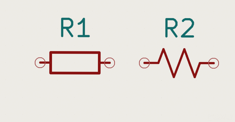
Align Components
Align components of the same type in the same direction to minimize assembly errors and simplify production inspections.
-
Manage Heat
Distribute heat-generating components evenly for optimal heat dissipation and separate temperature-sensitive parts from heat sources to prevent performance issues.
-
Minimize Trace Length
Reduce connection distance, especially for critical signals, and separate high-voltage traces from low-voltage ones to avoid interference and signal degradation.
Conclusion
Adhering to these principles ensures efficient, reliable, and manufacturable PCB designs by considering component importance, heat management, signal integrity, and maintenance ease.
Decoupling Capacitor Layout
Proper placement of decoupling capacitors near IC power supply pins minimizes noise and voltage fluctuations, ensuring stable power delivery and reducing high-frequency noise for improved signal quality.
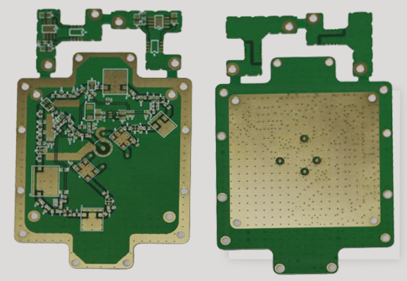
Component Grouping for Power Supply Segregation
PCB Layout Design Best Practices
When creating a PCB layout, it is crucial to consider the future potential for power supply separation. By grouping components that share the same power supply in close proximity, you can easily manage power distribution and isolation in future revisions. This not only aids in thermal management but also allows for the addition of separate power domains if necessary. A well-organized layout simplifies the routing process, ensuring efficient use of PCB space, which is especially vital for intricate designs with multiple power rails.
Right-Angle Routing: A Design Pitfall
Avoid using right-angle routing in PCB design as it can harm signal integrity. Right angles cause impedance discontinuities, leading to signal reflection and potential degradation. Issues with right-angle traces include:
- Capacitive Loading: Sharp corners act as capacitive loads, slowing down high-speed signal rise time.
- Impedance Discontinuity: Sudden trace direction changes create impedance mismatches, affecting signal reflection and integrity.
- Electromagnetic Interference (EMI): Abrupt trace direction changes generate unwanted electromagnetic radiation, contributing to EMI.
To maintain signal integrity, opt for smooth trace routing with gradual bends instead of right angles. This choice ensures more reliable and high-performance PCB designs.
Differential Signal Routing: Key Considerations
Differential signaling is crucial in high-speed PCB design for superior noise immunity and signal integrity. In differential signaling, two complementary signals transmit on a trace pair, with the receiver detecting the logical state by measuring the voltage difference. Advantages of differential signaling include:
- Enhanced Noise Immunity: Common-mode noise cancellation due to similar noise effects on both traces.
- Reduced EMI: Electromagnetic field cancellation from opposite signal polarities minimizes EMI.
- Improved Timing Accuracy: Less influenced by temperature variations, ensuring accurate timing, especially in LVDS applications.
For effective differential routing, maintain equal length and spacing in the differential pairs. Equal length preserves signal phase and differential nature, while equal spacing maintains impedance consistency and reduces reflections. Keep traces close to each other for strong signal coupling and improved quality.
Snake Lines: Managing Delay and Signal Integrity
Snake line routing adjusts signal delays and aligns timing in PCB design but should be used cautiously to prevent signal quality degradation and increased transmission delay. While snake lines can be necessary for timing adjustments, excessive winding should be avoided to maintain signal integrity. Balance is key to adjusting signal delay without compromising performance.
Understanding and applying these routing principles can optimize signal integrity, reduce EMI, and ensure reliable high-speed operation in PCB designs. Every decision, from capacitor placement to differential trace routing, plays a vital role in achieving high PCB performance.
If you have any questions about PCB or PCBA, feel free to contact me at info@wellcircuits.com.