1. As a PCB design engineer, having knowledge of high-speed signaling is not only important but also essential. High-speed signals are typically found in various parallel and serial buses. Understanding what a bus is will help you determine how fast it operates, and from there, you can begin your PCB layout design.
2. **Bus**
A bus is a shared physical pathway used for communication between two or more devices. It consists of a set of signal lines that provide a common connection between multiple components, facilitating the transmission of data between them. Depending on how the bus operates, it can be categorized into two types: parallel and serial buses.
3. **Parallel Bus**
In a parallel bus, multiple bits of data can be transmitted simultaneously. This is similar to a wide road where multiple cars can travel side by side, with both one-way and two-way traffic patterns.
4. **Serial Bus**
In contrast, a serial bus transmits data one bit at a time, typically over fewer signal lines. While this may seem slower compared to a parallel bus, serial buses are often favored for long-distance communication due to their simpler wiring and better noise immunity.

**Only one piece of data can be transmitted at a time, much like a narrow road that allows only one car to pass. The data must be transmitted sequentially, creating a long string of data, which is why it’s called “serial.”**
An ideal example of parallel transmission is found in DDR memory chips. These chips have a set of data lines, D0-D7, along with DQS and DQM. These lines transmit data simultaneously. If any bit encounters an error, the entire data set is corrupted and must be retransmitted. As a result, each data line must be of equal length, and the wires are often wound multiple times to minimize timing mismatches.
Serial data transmission works differently. Data is sent bit by bit, with no interdependence between bits. If one bit encounters an error, it does not affect the transmission of the subsequent bit. In contrast, with parallel data, if one bit fails, the entire data set becomes invalid.
**PCB Wiring Requirements**
*Parallel Bus Wiring Requirements*:
(1) It is recommended that the bus be routed internally, and that the distance between the bus and other traces be maximized to reduce interference.
(2) Unless there are special design requirements, single-ended traces should maintain an impedance of 50 ohms, while differential traces should have an impedance of 100 ohms.
(3) It is recommended that all traces in the same bus group be of equal length, with a consistent timing relationship to the clock line. Trace length should be controlled according to the results of detailed timing analysis.
(4) To ensure reference plane integrity, the bus should be routed as close as possible to the I/O power or ground plane.
(5) For buses with rise times under 1 ns, a continuous reference plane is required, and the traces must not cross any partitions.
(6) The lower address bus should adhere to the same routing guidelines as the clock lines.
(7) The spacing for serpentine traces should be at least three times the trace width.
**High-Speed PCB Serial Bus Wiring Requirements**
For serial buses operating at frequencies above 100 Mbps, additional considerations must be taken into account, alongside the general crosstalk control and routing guidelines for parallel buses:
(1) The loss of signal integrity due to trace resistance must be considered, and the trace width and length should be optimized accordingly.
(2) Under normal circumstances, it is recommended that trace widths be no smaller than 5 mils, and traces should be kept as short as possible to minimize signal degradation.
(3) High-speed serial buses should avoid unnecessary vias, except for fan-out vias, to reduce signal reflection and loss.
(4) For serial buses operating at speeds above 3.125 Gbps, it’s important to optimize the anti-pad design to minimize impedance discontinuities and reduce signal radiation.
(5) When changing signal layers for high-speed serial buses, select the layer with the shortest via stub to minimize signal loss. If space is constrained, prioritize routing the sending end of the signal on the layer with the shortest via stub.
(6) For speeds of 3.125 Gbps or higher, it is advisable to drill a ground hole next to the signal via, and to carefully manage the anti-pad for the AC coupling capacitors.
(7) If high-speed signal vias are back-drilled, consider the impact of reducing the current capacity of the power ground plane, as well as the increased inductance of the filter loop due to narrowed flow bottlenecks.
(8) High-speed signals should avoid crossing the boundary lines between planes. Ensure the horizontal distance between the signal trace and the edge of the dividing line is at least 3 times the trace width (3W).
(9) High-speed signals in both directions should not be routed on the same layer or cross each other.
If you have any PCB manufacturing needs, please do not hesitate to contact me.Contact me
2. **Bus**
A bus is a shared physical pathway used for communication between two or more devices. It consists of a set of signal lines that provide a common connection between multiple components, facilitating the transmission of data between them. Depending on how the bus operates, it can be categorized into two types: parallel and serial buses.
3. **Parallel Bus**
In a parallel bus, multiple bits of data can be transmitted simultaneously. This is similar to a wide road where multiple cars can travel side by side, with both one-way and two-way traffic patterns.
4. **Serial Bus**
In contrast, a serial bus transmits data one bit at a time, typically over fewer signal lines. While this may seem slower compared to a parallel bus, serial buses are often favored for long-distance communication due to their simpler wiring and better noise immunity.
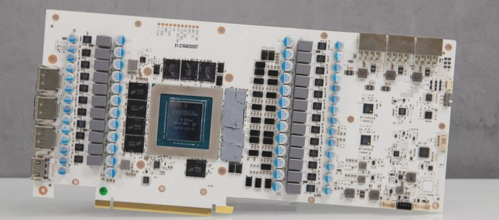
**Only one piece of data can be transmitted at a time, much like a narrow road that allows only one car to pass. The data must be transmitted sequentially, creating a long string of data, which is why it’s called “serial.”**
An ideal example of parallel transmission is found in DDR memory chips. These chips have a set of data lines, D0-D7, along with DQS and DQM. These lines transmit data simultaneously. If any bit encounters an error, the entire data set is corrupted and must be retransmitted. As a result, each data line must be of equal length, and the wires are often wound multiple times to minimize timing mismatches.
Serial data transmission works differently. Data is sent bit by bit, with no interdependence between bits. If one bit encounters an error, it does not affect the transmission of the subsequent bit. In contrast, with parallel data, if one bit fails, the entire data set becomes invalid.
**PCB Wiring Requirements**
*Parallel Bus Wiring Requirements*:
(1) It is recommended that the bus be routed internally, and that the distance between the bus and other traces be maximized to reduce interference.
(2) Unless there are special design requirements, single-ended traces should maintain an impedance of 50 ohms, while differential traces should have an impedance of 100 ohms.
(3) It is recommended that all traces in the same bus group be of equal length, with a consistent timing relationship to the clock line. Trace length should be controlled according to the results of detailed timing analysis.
(4) To ensure reference plane integrity, the bus should be routed as close as possible to the I/O power or ground plane.
(5) For buses with rise times under 1 ns, a continuous reference plane is required, and the traces must not cross any partitions.
(6) The lower address bus should adhere to the same routing guidelines as the clock lines.
(7) The spacing for serpentine traces should be at least three times the trace width.
**High-Speed PCB Serial Bus Wiring Requirements**
For serial buses operating at frequencies above 100 Mbps, additional considerations must be taken into account, alongside the general crosstalk control and routing guidelines for parallel buses:
(1) The loss of signal integrity due to trace resistance must be considered, and the trace width and length should be optimized accordingly.
(2) Under normal circumstances, it is recommended that trace widths be no smaller than 5 mils, and traces should be kept as short as possible to minimize signal degradation.
(3) High-speed serial buses should avoid unnecessary vias, except for fan-out vias, to reduce signal reflection and loss.
(4) For serial buses operating at speeds above 3.125 Gbps, it’s important to optimize the anti-pad design to minimize impedance discontinuities and reduce signal radiation.
(5) When changing signal layers for high-speed serial buses, select the layer with the shortest via stub to minimize signal loss. If space is constrained, prioritize routing the sending end of the signal on the layer with the shortest via stub.
(6) For speeds of 3.125 Gbps or higher, it is advisable to drill a ground hole next to the signal via, and to carefully manage the anti-pad for the AC coupling capacitors.
(7) If high-speed signal vias are back-drilled, consider the impact of reducing the current capacity of the power ground plane, as well as the increased inductance of the filter loop due to narrowed flow bottlenecks.
(8) High-speed signals should avoid crossing the boundary lines between planes. Ensure the horizontal distance between the signal trace and the edge of the dividing line is at least 3 times the trace width (3W).
(9) High-speed signals in both directions should not be routed on the same layer or cross each other.
If you have any PCB manufacturing needs, please do not hesitate to contact me.Contact me

