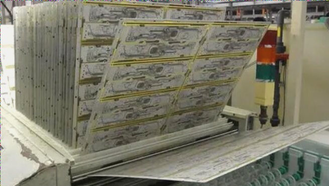
Understanding IPC Standards in PCB Assembly
IPC, originally standing for ‘Institute for Print Circuits,’ now known as the Electronic Industries Connectivity Consortium, sets the standards for PCB assembly in various industries such as aerospace, automotive, and telecommunications.
These standards are crucial in ensuring reliability, quality, and high performance in the design and manufacturing of PCBs and electronic assemblies.
Importance of PCB Assembly Standards
The standards set by IPC are essential to guarantee the safety, reliability, and performance of PCB-related products. Adhering to these standards throughout the manufacturing process is key to maintaining quality and commitment.
Many PCB manufacturers utilize these standards to meet customer expectations, improve reliability, and enhance the overall manufacturing process.
Benefits of Adhering to IPC Standards
- Enhanced communication with employees and suppliers
- Cost reduction
- Improved reputation and new opportunities
Key Elements of IPC Standards
IPC standards cover various aspects of PCB manufacturing, including:
- Acceptance testing
- Assembly processes
- Resistance coatings
- Integrated Circuits (IC)
- Flexible strength
- Critical activities
Implementing PCB Assembly Standards
Following the prescribed procedures outlined by IPC is crucial for achieving high-quality and reliable end products. The assembly process involves steps such as attaching eyelets, mounting components, soldering, and quality checks.
Advancements in PCB Assembly Technology
With the support of CAM/CAD technology, human errors during manual mounting are significantly reduced. However, incorrect loading by personnel can result in mass errors due to device shape.
Variety of PCB Assembly Components
The mechanical structure of PCB components is intricate, requiring technicians to be skilled and meticulous in adjusting and aligning the machinery for maintenance and repair work.
Each component’s unique external shape structure poses challenges in grouping and attaching them correctly, impacting productivity.
While soldering component legs improves joint quality, it also complicates repairs, necessitating careful handling to prevent damage to the PCB.
Despite the need for error correction pins, the reduced number of remaining pins simplifies the debugging process.
Evolution of PCB Assembly Technology
As electronic products demand smaller and denser components, traditional legged components have transitioned to compact CHIPs, requiring automated assembly processes.
Surface-mount technology (SMT) emerged in the late 1980s to accommodate the miniaturization and densification of electronic circuits, reducing manual intervention.
Auto-Mount or SMT Technology
Initially developed by IBM in the 1960s for space program computers, SMT allows for the surface mounting of CHIP components on PCBs, enhancing circuit compactness.
Supporting technologies like glue dispensing aid in securing components during the assembly process, ensuring precise placement and soldering.
Primary PCB Assembly Procedures
- Plug the eyelet (or asterisk, rivet, etc.)
- Install jumper wires
- Insert coaxial (axial) components
- Mount asynchronous (radial) components
- Attach components of varying shapes
- Apply glue to affix CHIP components
- Utilize a dispenser for precise application
- Print solder paste for CHIP components
- Place IC components if necessary
- Perform reflow soldering
- Address components that cannot be inserted
- Conduct wave soldering
- Trim legs for corrections
- Thoroughly inspect and adjust the assembly
Modern component miniaturization has eliminated through-hole plugging, streamlining the assembly process to focus on solder paste application and component placement.
- Print solder paste on the PCB
- Place CHIP components
- Add IC components
- Perform reflow soldering
For the other side, repeat the following steps:
- Apply CHIP components
- Insert IC components
- Conduct reflow soldering
- Hand solder non-glued components (potentially through-hole components)
- Limitations in PCB Assembly Process
- Solder Paste Application on Copper PCB Circuits
PCB Assembly Process Improvement
One challenge with this approach is that the initial reflow may lead to errors in back gluing, impacting the solder joint integrity from subsequent reflows.
A solution to this issue is the utilization of SMT plug technology, enabling printing and gluing on both sides with a single reflow process.
Each combination of technologies requires a tailored process, considering specific materials, tools, and supporting machinery. Production organization demands expertise and technical acumen.
This results in diverse processes that yield high-quality products; for instance, manufacturing a flexible board necessitates the use of different jig mounts for support. While an SMT machine can handle a standard 1.6mm thick rigid PCB, a soft board, at 0.09mm thickness and flexible nature, requires special considerations.
Solder paste printing is a crucial step in the PCB assembly process.
As components shrink in size, the challenges in solder paste printing quality and technology control intensify. Some manufacturers have introduced devices that glue components onto PCBs using FLUX as an adhesive.
Solder is pre-applied to component poles/pins, and the device then applies solder paste into the FLUX, affixing the component onto the PCB for reflow soldering.
Despite advancements, many companies still combine Auto-Insert and SMT technologies, using both SMT glue and solder paste, or a mix of AI, SMT glue, and solder paste. The sequence may involve SMT preceding AI or vice versa.
Companies with ample capital and a focus on quality opt for modern SMT technology over conventional methods.
Summary
Understanding and mastering current PCB assembly processes is vital for technicians, engineers, and workers in electronics manufacturing. They must continuously learn and adapt to produce efficient electronic circuits on PCBs.
This knowledge also aids production and quality managers in enhancing production processes and quality control measures.

