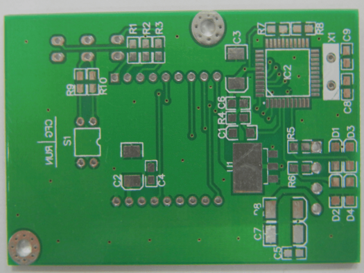
Essential Guidelines for Testing PCB Boards
- Do not use grounded test equipment to contact live TV, audio, video, and other equipment on the PCB without an isolation transformer.
- Pay attention to the insulation performance of the soldering iron and use a low-voltage electric soldering iron for safety.
- Understand the integrated circuit and related circuits before testing the PCB board.
- Avoid causing short circuits between pins while testing and use a test instrument with high internal resistance.
- Monitor the heat dissipation of the power integrated circuit during testing.
- Ensure reasonable lead detection and verify soldering quality on the PCB board.
- Avoid hastily judging integrated circuit damage.
PCB Board Debugging Method
When debugging a newly acquired PCB board, start by checking for visible issues like cracks, short circuits, or open circuits. Verify the resistance between the power supply and ground if necessary.
For a newly designed circuit board, follow these steps:
- Inspect the new PCB board for cracks, short circuits, or open circuits. Check the resistance between the power supply and ground wire.
- Install components carefully and test each module independently to ensure normal operation.
- Gradually install other modules, powering on and testing after each installation to prevent overcurrent and component damage.
Additional Information:
When testing PCB boards, always ensure proper safety measures are in place to prevent damage to components and circuits. It is essential to follow industry best practices to guarantee the quality and functionality of the PCB boards.
Moreover, staying updated with the latest advancements in PCB fabrication technologies can help improve testing and debugging processes, leading to more efficient and reliable circuit board production.
Methods to Identify PCB Faults
- Measure Voltages:
- Utilize Signal Injection:
- Explore Other Detection Techniques:
Check power supply pins for normal voltage levels. Verify reference voltages and ensure correct working voltages at different points on the PCB. For instance, in a silicon transistor, the BE junction voltage should be approximately 0.7V, while the CE junction voltage should be around 0.3V or lower. An excessively high BE junction voltage could signal an open junction.
Inject a signal at the input terminal and analyze waveforms at various points to pinpoint faults. Alternatively, lightly touch input terminals with a tweezer to observe output responses. (Caution: Avoid this method for high-voltage circuits due to potential shock hazards.) A response upon touching indicates a fault in the preceding stages.
Conduct a visual inspection to look for mechanical damage such as cracks or burns. Listen for unusual sounds and smell for any atypical odors, including burning smells or capacitor electrolyte scents. Experienced technicians should pay attention to detecting unusual odors as they can be indicative of faults. Monitor component temperatures as overheated or excessively cool components may suggest underlying issues. Typically, power transistors and voltage regulators should operate below 70 degrees Celsius for optimal performance.


