### PCB Substrate Design Principles
In PCB circuit board design, the substrate design plays a critical role in ensuring proper electrical performance and reliability. Below are the key principles and best practices for substrate design:
1. **Pad Alignment and Direction**
In the substrate design, the pads of the DIE must align with the direction of the bonding wires. Additionally, the lead wires must also align with the pads. For each DIE, a cross-shaped pad should be placed along its diagonal as an alignment reference when binding. The coordinates of this cross must be connected to the network of the attachment. When choosing the location for this cross, ensure that the network is present; otherwise, the cross will not be created. Furthermore, to prevent the cross from being obscured by copper, it is typically recommended to avoid laying copper around it, ensuring clear visibility.
**Pad Deletion for Unused Pins**
Any unused pads, i.e., those not connected to the network, must be removed from the design. This ensures that there is no unnecessary copper on the board, preventing potential issues with signal integrity and minimizing the risk of shorts or unwanted capacitance.
2. **Electroplating Process for Copper Pads and Traces**
The production of PCB substrates requires a specialized process where each trace is created by electroplating copper. This process forms the copper pads and traces, as well as any other copper areas on the board. It is important to note that even if there is no electrical connection (i.e., no network), the pads must still be extended out from the board frame to allow copper plating during the eco-mode process. Failure to do so may result in the pads being left without copper, which could compromise the board’s integrity and performance.
By adhering to these principles, you can ensure that the substrate design is optimized for both electrical functionality and manufacturing efficiency. Proper alignment, careful pad management, and a thorough understanding of the electroplating process are essential for high-quality PCB design.

### 1. Electroplated Copper Skin and Corrosion Protection
The electroplated wire, drawn out from the board frame, should have a copper skin on the opposite layer to indicate its corrosion position. This copper layer is typically the seventh layer of copper. In general, the copper sheet extends 0.15mm beyond the inner side of the board frame, with a distance of approximately 0.2mm between the copper-laid edge and the board frame.
### 2. Positive and Negative Polarity in the Board Frame
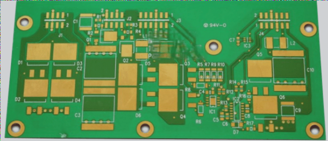
To correctly identify the positive and negative sides of the board, it is recommended to place all components on the same side, which should be marked with three “XXX,” as illustrated in the accompanying diagram. This ensures clear identification and alignment.
### 3. Pad Sizes and Layout for Special Packages
Pads used on the substrate are larger than standard ones, especially for special packages like CX0201, which differ from the C0201 package. The pad dimensions are organized as follows:
– **0603 Pad**: 1.02mm x 0.92mm, with an open window area of 0.9mm x 0.8mm. The distance between pads is 1.5mm.
– **0402 Pad**: 0.62mm x 0.62mm, with an open window area of 0.5mm x 0.5mm. The distance between pads is 1.0mm.
– **0201 Pad**: 0.42mm x 0.42mm, with an open window area of 0.3mm x 0.3mm. The distance between pads is 0.55mm.
### 4. Die Pad and Wire Bonding Requirements
For Die pads, the following criteria apply:
– The minimum bonding pad size (single wire) should be 0.2mm x 0.09mm at a 90-degree angle.
– The spacing between pads should be at least 2 mils (0.051mm).
– The inner row pads for ground and power lines must have a width of 0.2mm.
– Bonding pad angles should align with the component wire pull angle.
– When constructing the substrate, binding wires should not be excessively long.
– The minimum distance between the main control Die and the inner bonding pad is 0.4mm, and for FLASHDIE, it is 0.2mm.
– The maximum allowable binding wire length between the two dies should not exceed 3mm.
– Spacing between rows of bonding pads should be at least 0.27mm.
### 5. Clearance Between SMT Pads, DIE Pads, and Components
Ensure the following clearances:
– The distance between an SMT pad, DIE bonding pad, and SMT component should be at least 0.3mm.
– The spacing between bonding pads of different Dies should be at least 0.2mm.
– The minimum signal trace width should be 2 mils (0.051mm), with at least 2 mils of spacing.
– The width of the main power line should be between 6 to 8 mils (0.152mm to 0.203mm).
– Ground areas should be kept as large as possible, and where ground planes are not feasible, power and signal lines should be used to reinforce the substrate’s strength.
### 6. Via and Pad Spacing Guidelines
Special attention should be paid to vias and pads when routing the PCB.
– Gold fingers should not be placed too close to one another.
– Vias and gold fingers of the same type must be spaced at least 0.12mm apart.
– For vias of different attributes, maintain the greatest possible distance from pads and gold fingers.
– The minimum via hole size for outer layers is 0.35mm, while for inner layers, it is 0.2mm.
– When routing copper, ensure that copper traces are not too close to gold fingers. Remove any broken copper, and avoid leaving large uncovered areas where copper is needed.
### 7. Copper Pour Grid Ratio
When laying copper, a grid pattern should be applied with a ratio of 1:4. Specifically, the copper pour angle of **COPPERPOUR** should be 0.1mm, and **COPPER** should be 0.4mm, rather than the typical 45-degree angle. This grid layout ensures a more stable and efficient copper distribution across the PCB.
In PCB circuit board design, the substrate design plays a critical role in ensuring proper electrical performance and reliability. Below are the key principles and best practices for substrate design:
1. **Pad Alignment and Direction**
In the substrate design, the pads of the DIE must align with the direction of the bonding wires. Additionally, the lead wires must also align with the pads. For each DIE, a cross-shaped pad should be placed along its diagonal as an alignment reference when binding. The coordinates of this cross must be connected to the network of the attachment. When choosing the location for this cross, ensure that the network is present; otherwise, the cross will not be created. Furthermore, to prevent the cross from being obscured by copper, it is typically recommended to avoid laying copper around it, ensuring clear visibility.
**Pad Deletion for Unused Pins**
Any unused pads, i.e., those not connected to the network, must be removed from the design. This ensures that there is no unnecessary copper on the board, preventing potential issues with signal integrity and minimizing the risk of shorts or unwanted capacitance.
2. **Electroplating Process for Copper Pads and Traces**
The production of PCB substrates requires a specialized process where each trace is created by electroplating copper. This process forms the copper pads and traces, as well as any other copper areas on the board. It is important to note that even if there is no electrical connection (i.e., no network), the pads must still be extended out from the board frame to allow copper plating during the eco-mode process. Failure to do so may result in the pads being left without copper, which could compromise the board’s integrity and performance.
By adhering to these principles, you can ensure that the substrate design is optimized for both electrical functionality and manufacturing efficiency. Proper alignment, careful pad management, and a thorough understanding of the electroplating process are essential for high-quality PCB design.
### 1. Electroplated Copper Skin and Corrosion Protection
The electroplated wire, drawn out from the board frame, should have a copper skin on the opposite layer to indicate its corrosion position. This copper layer is typically the seventh layer of copper. In general, the copper sheet extends 0.15mm beyond the inner side of the board frame, with a distance of approximately 0.2mm between the copper-laid edge and the board frame.
### 2. Positive and Negative Polarity in the Board Frame
To correctly identify the positive and negative sides of the board, it is recommended to place all components on the same side, which should be marked with three “XXX,” as illustrated in the accompanying diagram. This ensures clear identification and alignment.
### 3. Pad Sizes and Layout for Special Packages
Pads used on the substrate are larger than standard ones, especially for special packages like CX0201, which differ from the C0201 package. The pad dimensions are organized as follows:
– **0603 Pad**: 1.02mm x 0.92mm, with an open window area of 0.9mm x 0.8mm. The distance between pads is 1.5mm.
– **0402 Pad**: 0.62mm x 0.62mm, with an open window area of 0.5mm x 0.5mm. The distance between pads is 1.0mm.
– **0201 Pad**: 0.42mm x 0.42mm, with an open window area of 0.3mm x 0.3mm. The distance between pads is 0.55mm.
### 4. Die Pad and Wire Bonding Requirements
For Die pads, the following criteria apply:
– The minimum bonding pad size (single wire) should be 0.2mm x 0.09mm at a 90-degree angle.
– The spacing between pads should be at least 2 mils (0.051mm).
– The inner row pads for ground and power lines must have a width of 0.2mm.
– Bonding pad angles should align with the component wire pull angle.
– When constructing the substrate, binding wires should not be excessively long.
– The minimum distance between the main control Die and the inner bonding pad is 0.4mm, and for FLASHDIE, it is 0.2mm.
– The maximum allowable binding wire length between the two dies should not exceed 3mm.
– Spacing between rows of bonding pads should be at least 0.27mm.
### 5. Clearance Between SMT Pads, DIE Pads, and Components
Ensure the following clearances:
– The distance between an SMT pad, DIE bonding pad, and SMT component should be at least 0.3mm.
– The spacing between bonding pads of different Dies should be at least 0.2mm.
– The minimum signal trace width should be 2 mils (0.051mm), with at least 2 mils of spacing.
– The width of the main power line should be between 6 to 8 mils (0.152mm to 0.203mm).
– Ground areas should be kept as large as possible, and where ground planes are not feasible, power and signal lines should be used to reinforce the substrate’s strength.
### 6. Via and Pad Spacing Guidelines
Special attention should be paid to vias and pads when routing the PCB.
– Gold fingers should not be placed too close to one another.
– Vias and gold fingers of the same type must be spaced at least 0.12mm apart.
– For vias of different attributes, maintain the greatest possible distance from pads and gold fingers.
– The minimum via hole size for outer layers is 0.35mm, while for inner layers, it is 0.2mm.
– When routing copper, ensure that copper traces are not too close to gold fingers. Remove any broken copper, and avoid leaving large uncovered areas where copper is needed.
### 7. Copper Pour Grid Ratio
When laying copper, a grid pattern should be applied with a ratio of 1:4. Specifically, the copper pour angle of **COPPERPOUR** should be 0.1mm, and **COPPER** should be 0.4mm, rather than the typical 45-degree angle. This grid layout ensures a more stable and efficient copper distribution across the PCB.