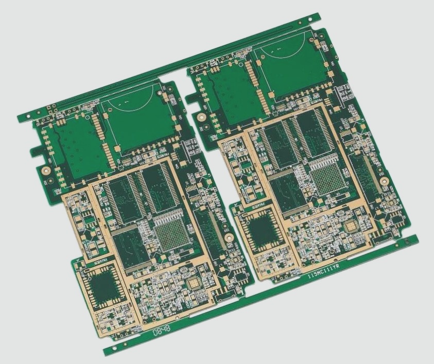
1. How many of the 9 general knowledge about PCB board prototyping do you know? Here are these 9 common knowledge you should know, and the specifics should be discussed with the PCB board prototyping manufacturer.

1. When inspecting a PCB board, ensure the electric soldering iron’s insulation performance is sufficient. Never solder with a powered soldering iron; always ensure it’s uncharged. Grounding the soldering iron’s shell is advisable, especially when working with MOS circuits. For added safety, opt for a low-voltage (6~8V) circuit iron.
2. Prior to testing a PCB board, grasp the operational principles of integrated circuits and related circuits. Familiarize yourself with the integrated circuit’s function, internal circuitry, key electrical parameters, pin functionalities, normal pin voltages, waveforms, and peripheral component circuitry. Fulfilling these prerequisites significantly eases analysis and inspection processes.
3. Under no circumstances should grounded test equipment directly contact live TV, audio, or video equipment on the PCB board without an isolation transformer. Testing such equipment without a power isolation transformer using grounded enclosures can lead to short circuits, affecting integrated circuits and potentially exacerbating faults.
4. The test instrument for PCB board internal resistance should possess high resistance. When measuring IC pin DC voltages, employ a multimeter with a meter head internal resistance exceeding 20KΩ/V. Otherwise, significant measurement errors may occur for certain pin voltages.
5. While testing PCB boards, monitor the heat dissipation of power integrated circuits closely. Adequate heat dissipation is imperative for power integrated circuits, and operating them without a heat sink in high-power states is not permissible.
6. Ensure soldering quality during PCB board testing. Firm solder joints are essential; excessive solder accumulation or pores can lead to false soldering. Limit soldering time to no more than 3 seconds, using an internally heated soldering iron with approximately 25W power. Inspect soldered integrated circuits meticulously, verifying absence of solder bridges with an ohmmeter before powering on.
7. Rational testing of PCB board lead wires is crucial. When adding external components to replace damaged integrated circuit parts, opt for small components and arrange wiring logically to mitigate unnecessary parasitic coupling, especially regarding grounding between the audio power amplifier integrated circuit and the preamplifier circuit.
8. Avoid hastily diagnosing integrated circuit damage during PCB board testing. Many integrated circuits are directly coupled, meaning a single abnormality could cause multiple voltage fluctuations, not necessarily indicating integrated circuit damage. Furthermore, deviations from normal pin voltages may not always signify integrated circuit malfunction, as some faults may not affect DC voltage.
9. Prevent pin short circuits during PCB board testing. When measuring voltage or waveform with an oscilloscope probe, avoid pin short circuits due to test lead or probe slippage. Direct measurement on the peripheral printed circuit connected to the pins is recommended. Any momentary short circuit can potentially harm the integrated circuit, requiring extra caution when testing flat-package CMOS integrated circuits.


