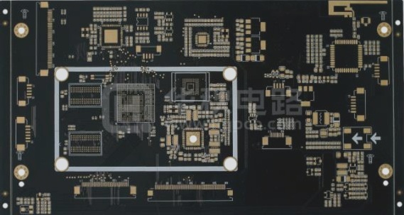
**1.** In PCB circuit design for electronic systems, effective anti-interference strategies are crucial. To avoid setbacks and save time, it is essential to thoroughly consider and address anti-interference requirements from the outset, rather than applying remedial measures after the design is finalized. There are three fundamental elements of interference:
**2.** (1) The interference source refers to the component, equipment, or signal that generates interference. Mathematically, it is expressed as Du / DT; when di / DT is substantial, it indicates a significant interference source. Examples include lightning, relays, thyristors, motors, and high-frequency clocks, which can all act as interference sources.
**3.** (2) The propagation path is the route or medium through which interference travels from the source to sensitive devices. Common propagation paths include conduction through wires and radiation through space.
**4.** (3) A sensitive device is one that is easily affected by interference. Examples include A/D and D/A converters, microcontrollers, digital ICs, and weak signal amplifiers.
**5.** The primary principle of anti-interference design involves suppressing the interference source, interrupting the propagation path, and enhancing the resilience of sensitive devices—much like measures taken to prevent infectious diseases.
**6.** 1. **Suppressing interference sources**
The goal of suppressing the interference source is to minimize the Du / dt and di / dt of that source. This is the top priority and a vital principle in anti-interference design, often yielding significant benefits with relatively low effort. Reducing the Du / dt of the interference source is primarily achieved by adding capacitors in parallel at both ends of the source. Meanwhile, reducing the di / dt is accomplished by incorporating inductance or resistance in series and adding a freewheeling diode to the interference source circuit.
—
Let me know if you need any further adjustments!

Common measures to suppress interference sources include the following:
(1) A freewheeling diode is added to the relay coil to eliminate the back EMF interference generated when the coil is disconnected. Simply adding a freewheeling diode may delay the relay’s disconnection time. However, with the addition of a zener diode, the relay can actuate more frequently in a given time frame.
(2) Connect a spark suppression circuit (typically an RC series circuit, with resistance values ranging from several K to tens of K and capacitance at 0.01μF) in parallel across the relay contacts to mitigate the effects of electric sparks.
(3) Integrate a filter circuit with the motor, ensuring that the leads for capacitance and inductance are kept as short as possible.
(4) Each IC on the circuit board should be connected in parallel with a high-frequency capacitor ranging from 0.01μF to 0.1μF to minimize the impact of the ICs on the power supply. It’s crucial to position the high-frequency capacitor wiring close to the power pin and keep it as thick and short as possible; otherwise, the equivalent series resistance may increase, negatively impacting filtering efficiency.
(5) Avoid using 90-degree bends in wiring to reduce high-frequency noise emissions.
(6) Attach an RC suppression circuit in parallel at both ends of the thyristor to lessen the noise generated by the thyristor, as severe noise may cause the thyristor to break down.
Interference can be classified based on its propagation path into conducted and radiated interference. Conducted interference refers to the noise transmitted to sensitive devices via wires. High-frequency interference noise exists in a different frequency band than useful signals; adding a filter on the conductor can effectively block high-frequency noise propagation, and sometimes an isolation optocoupler may also be incorporated. Power supply noise is particularly detrimental and requires careful management. Conversely, radiated interference refers to noise transmitted through space to sensitive devices. A common solution is to increase the distance between the interference source and the sensitive device, isolate them with grounding, and use shielding around the sensitive device.
The following are common strategies to sever interference propagation paths:
(1) Carefully consider the impact of the power supply on the MCU; addressing the power supply effectively resolves over half of the circuit’s overall interference issues. Many microcontrollers are quite sensitive to power supply noise, so incorporating a filter circuit or voltage regulator for the microcontroller’s power supply is advisable. For instance, a π-shaped filter circuit can be created using magnetic beads and capacitors. Alternatively, when conditions are less demanding, a 100Ω resistor can substitute for the magnetic beads.
(2) When using the I/O port of a microcontroller to control noisy devices like motors, it is essential to introduce isolation between the I/O port and the noise source, employing a π-shaped filter circuit.
(3) Pay careful attention to the wiring of the crystal oscillator; it should be placed as close as possible to the microcontroller pin, with the clock area isolated by grounding, and the crystal oscillator casing should be grounded and secured. This approach can resolve numerous challenging issues.
(4) The circuit board should be logically segmented into areas for strong and weak signals, as well as digital and analog signals. It’s important to position interference sources (like motors and relays) as far from sensitive elements (such as microcontrollers) as possible.
(5) Utilize ground wires to separate the digital area from the analog area, keeping the digital ground distinct from the analog ground, ultimately connecting both to the power ground at a single point. The routing of A/D and D/A chips should follow this principle, which manufacturers typically consider in their pin arrangements.
(6) The ground connections for the microcontroller and high-power devices should be made separately to minimize mutual interference, with high-power devices positioned towards the edge of the circuit board whenever possible.
(7) The anti-interference capability of the circuit can be significantly enhanced by employing anti-interference components like magnetic beads, magnetic rings, power filters, and shielding covers in critical locations such as MCU I/O ports, power lines, and circuit board connections.
### 3. Improving the Anti-Interference Performance of Sensitive Devices
Enhancing the anti-interference performance of sensitive devices involves strategies to minimize noise pickup and expedite recovery from abnormal states. Common measures include:
(1) During wiring, minimize the loop area to reduce induced noise.
(2) Ensure that the power line and ground wire are as thick as possible; this not only reduces voltage drop but also diminishes coupling noise.
(3) Idle I/O ports of microcontrollers should not be left floating; they should be grounded or connected to the power supply. Similarly, the unused terminals of other ICs should be grounded or connected to power without altering the system logic.
(4) Utilize power monitoring and watchdog circuits for microcontrollers, such as the IMP809, IMP706, and IMP813.


