PCB Factory: Repairing Circuit Boards
Introduction
With the increasing automation in machinery and equipment, the number of embedded boards in various industries has surged. When these boards get damaged, the high costs of replacement become a major concern for companies. This article explores methods for repairing circuit boards, including the classification of PCBs and inspection methods.
Classification of Circuit Boards
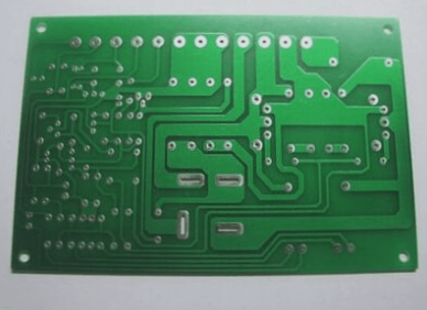
- Single-sided Aluminum Substrate: This basic PCB type has components on one side and transmission lines on the other. While cost-effective, it’s limited in complexity.
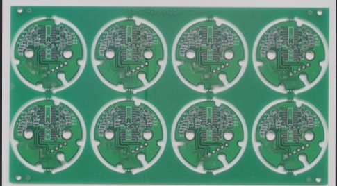
- Double-sided Board: Features copper plating and wiring on both sides, connected through vias for more complex electronic equipment.
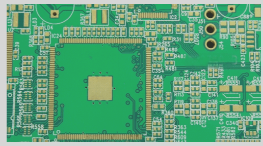
- Multi-layer Board: Composed of three or more conductive layers with insulating materials in between, ideal for high-speed and compact electronic applications.
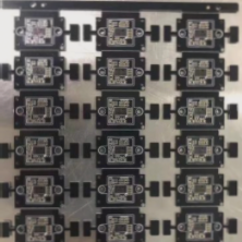
PCBs are also classified as flexible circuit boards (FPC), rigid boards (PCB), and rigid-flex hybrid boards (FPCB).
Circuit Board Inspection Methods

- Needle Bed Test Method: Uses a yellow electrode at each test point to maintain good contact and retrieve information for all test cases.
- Circuit Board Observation: Utilizes a handheld video microscope for detailed inspection of the circuit board’s structure.
- Two-Electrode Flying Probe Test Method: Employs movable electrodes to measure capacitors and detect short-circuit faults accurately.
- Visual Inspection: Initial step in repair process, checking for physical damage and burnt components on the board.
Understanding these methods is crucial for effectively repairing and maintaining circuit boards in various industries.
Static and Automatic Measurement Methods for PCB Maintenance
Static Data Measurement Method
- Check for short circuits between the switching power supply and ground using a digital multimeter.
- Verify the normal operation of diodes by measuring them with a multimeter.
- Test capacitors using the multimeter’s resistance function to detect any short circuits or faults.
- Measure integrated circuits, transistors, resistors, etc., with a digital multimeter to ensure they exhibit expected logical characteristics.
Visual inspection may not always reveal issues on circuit boards. When parts are physically deformed, a digital multimeter can accurately measure key components and identify faults. It is crucial to determine if the power circuit operates using digital or analog signals before proceeding with the static measurement method for digital circuits.
Automatic Measurement Method
- Categorize and isolate faulty electronic components based on issues identified during previous inspection steps.
- Utilize an automatic measurement system to compare good and bad circuit boards, detecting and correcting common faults.
Manufacturers producing circuit boards in high volumes often employ the automatic measurement method. They establish general adjustment and maintenance platforms that display key parameters, including the status of switching power supplies and essential raw data signals. This method efficiently addresses circuit board issues and ensures optimal performance.
Tips for PCB Maintenance:
After conducting visual and static data measurements, most circuit board problems can be resolved. It is essential to ensure the proper functioning of the switching power supply to avoid secondary damage during subsequent maintenance steps.