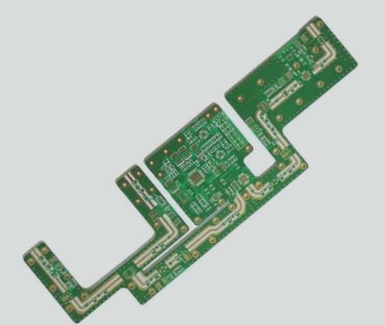
Protection Methods for PCB Electronic Products and Power Semiconductor Devices
-
Fuse Method
The fuse method is a common protection approach for PCB electronic circuits and equipment. A fuse is connected in series at the power input end of the circuit to regulate the total current. When a circuit issue occurs, the fault current flowing through the fuse increases, causing it to heat up and melt, cutting off the power supply for protection. While this method is simple, cost-effective, and ensures complete power cut-off during protection, it may not effectively respond to changes in the current of a single power semiconductor device due to its slow melting speed.

-
Main Circuit Current Detection Method
This method involves connecting detection elements in series with the main circuit power supply. It detects the current or voltage signal in the detection circuit, amplifies it, and compares it with the protection circuit’s threshold to determine whether to initiate protection. While offering improved sensitivity and response speed compared to the fuse method, it still detects the total circuit current, which may result in a delay between detection and protection action.
-
Detecting the Working Current of Power Devices
By placing a detection element in series with the working current path of the protected power semiconductor device, this method detects the working current to provide protection. It offers higher sensitivity and effectiveness compared to the main circuit current detection method. However, protection is still reactive and may lead to signal acquisition lag after a fault has occurred.
-
Parallel Detection of Power Device Voltage Method
In this method, the protection circuit is connected in parallel with the protected power device to detect its voltage during operation. By assessing the device’s voltage, the circuit can determine if a fault is present and cut off the control signal to the device for protection. This in-situ approach stops the device’s operation immediately to ensure protection.

Advantages of Parallel Type Detection Working Pressure Drop Method
- Protection circuit connected in parallel for high power utilization and no heat sources
- High input impedance, low power consumption, and high detection accuracy
- Highly targeted and provides timely, reliable protection
Disadvantage of Parallel Type Detection Working Pressure Drop Method
The protection circuit only offers qualitative detection, limiting protection to load short-circuits and severe over-current faults in voltage-controlled power devices.
Monitoring Voltage Drop for Overcurrent Assessment
Any overload or overcurrent in power semiconductor devices increases saturation voltage drop or working voltage drop, allowing assessment of the fault severity based on the magnitude of the voltage drop.
Continuous Advancements in PCB Power Devices
Ongoing research efforts drive technological progress, enhancing the efficiency of PCB electronic products and shaping the future of power devices.