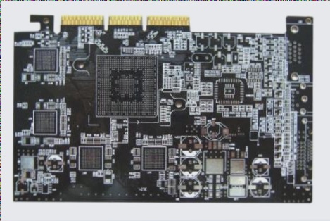
Visual Preview of Component Placement for PCB Manufacturing
Are you looking for a program that can provide a visual preview of component placing based on a pick and place output file, overlaid on an image of the board? While tools like Alciom SMT Assistant offer step-by-step placement guidance, you may need a solution that can draw outlines directly on the board image using centroid file data.
If you’ve designed a PCB using DipTrace and are facing challenges with importing it into Protel for manufacturing, you’re not alone. Some assembly houses require a visual preview for quality assurance purposes before loading components onto the machine. While the centroid file is sufficient for actual assembly, the lack of a visual verification step can lead to potential issues.
Unfortunately, finding a tool that can read DipTrace centroid files and overlay outlines on a board scan for visual inspection isn’t easy. However, not having this feature could result in the assembler attributing any placement issues to the use of a “non-standard PCB tool,” potentially shifting blame.
If you have successfully imported a DipTrace layout into Protel or know of a program that can meet the visual preview requirements, your insights would be valuable in resolving this dilemma.
Ensuring smooth component placement during PCB manufacturing is crucial, and having the right tools for visual validation can prevent delays and quality issues down the line.


