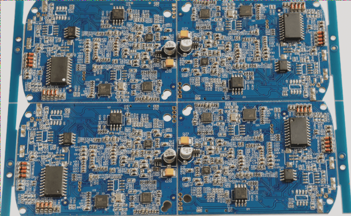
Component Positioning Methods and PCB Assembly
-
Capacitance
When dealing with electrolytic capacitors, the longer lead is positive, and the shorter lead is negative. Look for markings on the body and white stripes on the negative side parallel to the leads.

-
Capacitors
Methods to indicate polarity include marking the positive terminal with a “+” sign or using silk screening for the negative terminal area. Different approaches cater to different space and verification needs.
-
Diodes
For LEDs, the longer lead is positive, and a small notch may indicate the negative terminal. Various methods, such as using a “+” sign or silk-screen printing, help identify diode polarity on the board.
-
Integrated Circuits
Notches, marks, or dots are used to indicate the orientation of pins on DIP, SOIC, QFP, PLCC, and BGA packages. Different methods ensure proper alignment and orientation of integrated circuits on the PCB.
-
Other Components
Various methods like markings near the first pin, silk-screen circles, or triangles help ensure the correct orientation of through-hole components. Standards like IPC-7351 and IPC-SM-840 guide component placement for improved visibility and accuracy.

Understanding Polarity Markings for Components
When it comes to discrete components, polarity is typically denoted by lead length, silk-screen markings, or color coding. On the other hand, for integrated circuits, various methods are used to mark the first leg, such as concave dots, silk screening, notches, missing angles, or direct markings.
It is essential to pay attention to the design of pad graphics, ensuring that the component shape and positioning information match as closely as possible. Utilizing silk-screen printing can be beneficial in reducing assembly and soldering errors.
Latest Updates:
- New industry standards recommend incorporating QR codes on components for easy identification and tracking.
- Advanced PCB design software now offers automated polarity detection features, streamlining the design process.
- Manufacturers are exploring innovative ways to implement visual indicators for polarity, enhancing user-friendliness.