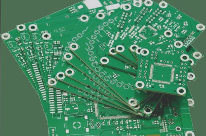
2. Electric vehicles are increasingly becoming a part of daily life in numerous major cities. Charging stations can now be spotted near factories and residences alike, making the circuit boards within these charging stations highly sought after.

1. Because the circuit board of the charging pile needs to withstand high current and high voltage during operation, conventional thin boards are inadequate. Although all PCB materials contain copper, there are significant grade differences.
2. Ordinary boards typically have a TG (glass transition temperature) below 140°C. The base material required for the new energy charging pile circuit board production needs to exceed TG150, utilizing high TG materials.
3. Data indicates that higher grade parameters correspond to superior panel quality.
It is not permissible to have line defects, residual copper on the edge of the line, yellowing of the impedance at the edge of the hole, etc. Manufacturers of charging pile circuit boards must also adhere to IPC-III standards to promptly eliminate products that fail to meet the standards.
The circuit boards used in new energy charging piles are designed for larger models, with current capacities incomparable to those of ordinary charging piles.
The output of a DC charging pile consists of 9 wires: “ground wire PE, DC power lines DC+ and DC-, communication lines S+ and S-, low-voltage auxiliary lines A+ and A-, and charging connection confirmation lines CC1 and CC2”. The DC charging pile completes the charging of electric vehicles by utilizing these 9 wires.
An essential aspect of the charging pile principle is “interface connection confirmation”. After the DC charging gun is inserted into the electric vehicle charger port, the charging pile monitoring point detects the voltage. Once a 4V voltage is detected, the charging pile determines successful connection of the charging interface and locks the electronic lock in the charging gun to prevent disconnection.
(3) Self-test of the DC charging pile:

When the charging port is successfully connected, the charging pile closes switches K3 and K4. This action turns on the low-voltage auxiliary circuit, supplying power to the electric vehicle control device. The electric vehicle then assesses the connection status based on the voltage at a monitoring point after receiving this power supply.
If the voltage reaches 6V, the vehicle will periodically send a handshake message. Subsequently, switches K1 and K2 are closed for insulation monitoring, ensuring the safety of the charging process by checking the insulation performance of the DC line. Following the insulation test, the bleed-off circuit is activated to dissipate any remaining energy, after which switches K1 and K2 are opened.

