The following is an overview of the failure probabilities and corresponding countermeasures for PCB capacitors:
1. Understanding the likelihood of different types of failures helps prioritize maintenance tasks, identify key focus areas, improve operational efficiency, reduce labor hours, and quickly pinpoint fault locations.
2. Based on actual PCB maintenance data, the failure probabilities for various equipment components are as follows: failures due to component damage make up one-third of the total failures, while failures from circuit board disconnections or corrosion also account for one-third. The remaining third of failures are attributed to issues such as program malfunctions or parameter adjustments.

1. **Generally speaking**, components subjected to high current and high voltage are the most prone to damage. These include parts like the fuse, rectifier bridge, switching transistors in the switching power supply, IGBTs in the frequency converter, driving optocouplers, and components in the PLC. Other susceptible components are output transistors, fuse resistors with higher power ratings, current-limiting resistors, and similar parts. These can be quickly checked in-circuit using the continuity test, resistance measurement, and diode testing functions of a multimeter.
2. **Nodes connected to external terminals** are also vulnerable to damage, such as the PLC input and output circuits, current detection interface circuits, and 485 communication interfaces. Because these parts are connected to transmission lines, they are more exposed to external shocks and interference, especially from the effects of frequent plugging and unplugging. One way to identify possible damage is by measuring the resistance at various points relative to a common terminal.
3. **Excluding high-current, high-voltage components and interface parts**, in a typical low-voltage DC circuit system, the probability of component failure generally follows this order: aluminum electrolytic capacitors, resistors, optocouplers, ceramic capacitors, relays, Zener diodes, transistors, tantalum capacitors, operational amplifiers, logic ICs, and processor chips.
4. **Aluminum electrolytic capacitors** are known to age over time, and their failure is almost inevitable. Typically, faulty capacitors range from 1μF to 330μF. Therefore, special attention should be paid to electrolytic capacitors that have been in service for several years.
5. **Common multimeters and capacitance meters** with a capacitance test function can measure the value of a capacitor, but even if the capacitance is unchanged, this doesn’t necessarily mean the capacitor is in good condition. The overall quality of the capacitor can only be assessed by additional parameters. In addition to measuring capacitance, a digital bridge can be used to test the capacitor’s loss factor, known as the D-value. If the D-value deviates significantly from the normal range, it indicates aging, and the capacitor should be replaced.
6. **The VI curve tester** is also an excellent tool for assessing the health of capacitors. The standard VI curve for a capacitor should resemble a symmetric ellipse centered at the origin. If the curve is distorted, this suggests that the capacitor’s ESR (equivalent series resistance) has increased due to aging.
7. **Resistors** typically fail by going open or exhibiting an unusually high resistance value. Using online testing, you can compare the measured resistance against the nominal value to determine whether a resistor is functioning properly.
8. **Optocoupler damage** is most commonly found in the driver section, and it can often be detected via online simulation.
9. **Ceramic capacitors** typically fail in one of two ways: as a short circuit or with minor leakage. An open circuit can sometimes be observed in SMD ceramic capacitors if the leads are corroded. Minor leakage is often undetectable. To diagnose, you can remove the suspected capacitor, measure its capacitance, and replace it with a new capacitor of the same value. Then, observe if the fault resolves when the circuit is powered. In analog circuits, small ceramic capacitors are often used for feedback filtering, and even a slight leakage can alter circuit behavior. If no major faults are found after checking all components, consider replacing these small ceramic capacitors as a troubleshooting step.
10. **Relay failure** typically occurs when the contacts become affected by arcing or oxidation, leading to poor connectivity or complete failure to operate. In severe cases, high current can weld the contacts together. You can assess the condition of the relay contacts by energizing the relay coil and measuring the resistance of the contacts.
11. **Zener diodes**, which are used to regulate voltage by consuming current, may fail if exposed to excessive current. Similarly, **TVS (transient voltage suppressor) diodes** in the circuit can also suffer damage under high current conditions.
If you have any PCB manufacturing needs, please do not hesitate to contact me.Contact me
1. Understanding the likelihood of different types of failures helps prioritize maintenance tasks, identify key focus areas, improve operational efficiency, reduce labor hours, and quickly pinpoint fault locations.
2. Based on actual PCB maintenance data, the failure probabilities for various equipment components are as follows: failures due to component damage make up one-third of the total failures, while failures from circuit board disconnections or corrosion also account for one-third. The remaining third of failures are attributed to issues such as program malfunctions or parameter adjustments.
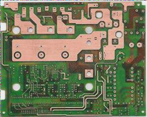
1. **Generally speaking**, components subjected to high current and high voltage are the most prone to damage. These include parts like the fuse, rectifier bridge, switching transistors in the switching power supply, IGBTs in the frequency converter, driving optocouplers, and components in the PLC. Other susceptible components are output transistors, fuse resistors with higher power ratings, current-limiting resistors, and similar parts. These can be quickly checked in-circuit using the continuity test, resistance measurement, and diode testing functions of a multimeter.
2. **Nodes connected to external terminals** are also vulnerable to damage, such as the PLC input and output circuits, current detection interface circuits, and 485 communication interfaces. Because these parts are connected to transmission lines, they are more exposed to external shocks and interference, especially from the effects of frequent plugging and unplugging. One way to identify possible damage is by measuring the resistance at various points relative to a common terminal.
3. **Excluding high-current, high-voltage components and interface parts**, in a typical low-voltage DC circuit system, the probability of component failure generally follows this order: aluminum electrolytic capacitors, resistors, optocouplers, ceramic capacitors, relays, Zener diodes, transistors, tantalum capacitors, operational amplifiers, logic ICs, and processor chips.
4. **Aluminum electrolytic capacitors** are known to age over time, and their failure is almost inevitable. Typically, faulty capacitors range from 1μF to 330μF. Therefore, special attention should be paid to electrolytic capacitors that have been in service for several years.
5. **Common multimeters and capacitance meters** with a capacitance test function can measure the value of a capacitor, but even if the capacitance is unchanged, this doesn’t necessarily mean the capacitor is in good condition. The overall quality of the capacitor can only be assessed by additional parameters. In addition to measuring capacitance, a digital bridge can be used to test the capacitor’s loss factor, known as the D-value. If the D-value deviates significantly from the normal range, it indicates aging, and the capacitor should be replaced.
6. **The VI curve tester** is also an excellent tool for assessing the health of capacitors. The standard VI curve for a capacitor should resemble a symmetric ellipse centered at the origin. If the curve is distorted, this suggests that the capacitor’s ESR (equivalent series resistance) has increased due to aging.
7. **Resistors** typically fail by going open or exhibiting an unusually high resistance value. Using online testing, you can compare the measured resistance against the nominal value to determine whether a resistor is functioning properly.
8. **Optocoupler damage** is most commonly found in the driver section, and it can often be detected via online simulation.
9. **Ceramic capacitors** typically fail in one of two ways: as a short circuit or with minor leakage. An open circuit can sometimes be observed in SMD ceramic capacitors if the leads are corroded. Minor leakage is often undetectable. To diagnose, you can remove the suspected capacitor, measure its capacitance, and replace it with a new capacitor of the same value. Then, observe if the fault resolves when the circuit is powered. In analog circuits, small ceramic capacitors are often used for feedback filtering, and even a slight leakage can alter circuit behavior. If no major faults are found after checking all components, consider replacing these small ceramic capacitors as a troubleshooting step.
10. **Relay failure** typically occurs when the contacts become affected by arcing or oxidation, leading to poor connectivity or complete failure to operate. In severe cases, high current can weld the contacts together. You can assess the condition of the relay contacts by energizing the relay coil and measuring the resistance of the contacts.
11. **Zener diodes**, which are used to regulate voltage by consuming current, may fail if exposed to excessive current. Similarly, **TVS (transient voltage suppressor) diodes** in the circuit can also suffer damage under high current conditions.
If you have any PCB manufacturing needs, please do not hesitate to contact me.Contact me

