PCB Negative Film Output Process
Understanding the difference between PCB positive film and negative film is crucial in the manufacturing process.
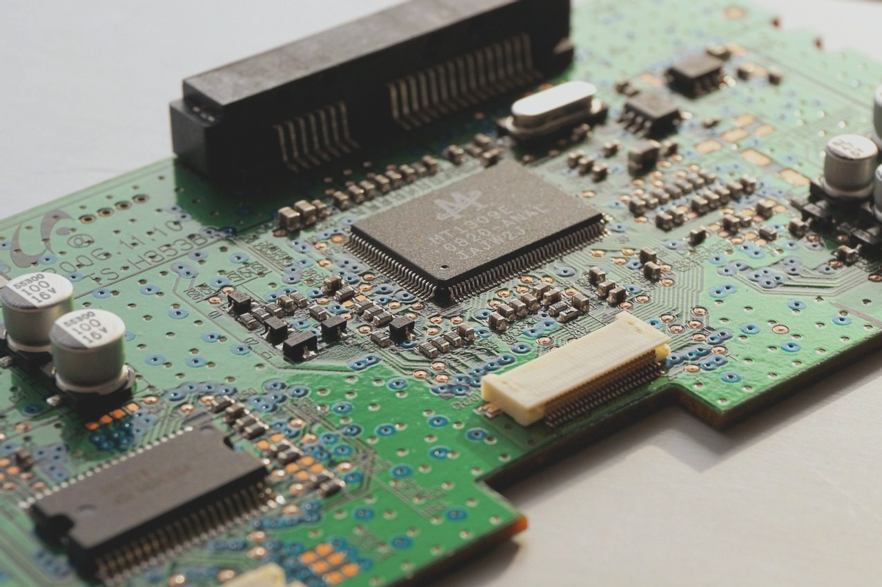
PCB Positive Film Function:
- Lines retain copper, while areas without lines remove copper.
- Primarily used for signal layers like top and bottom layers.
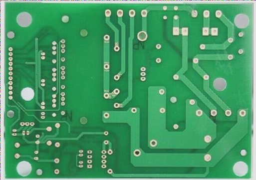
PCB Negative Film Function:
- Lines remove copper, while areas without lines retain copper.
- Mainly used for internal planes facilitating power and ground lines layout.
Negative Film Output Process

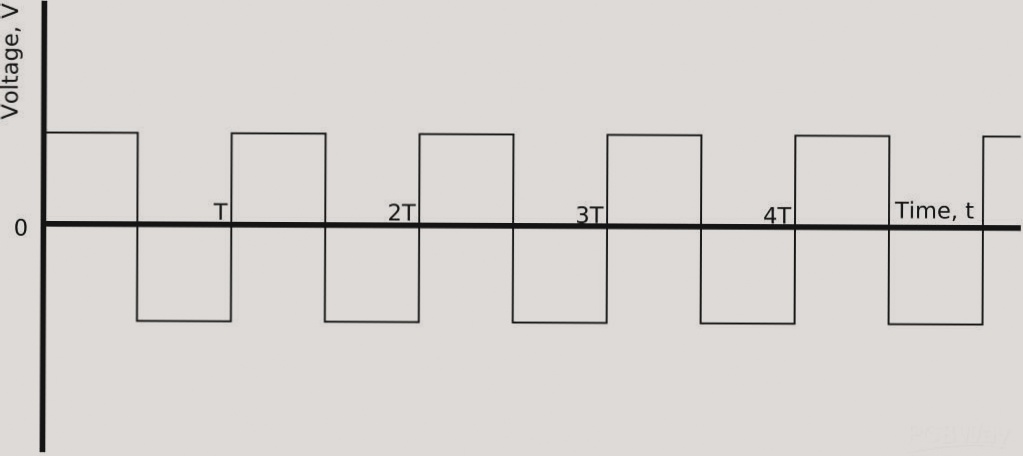
Negative Film Characteristics:
- Transparent circuit or copper surface with black/brown unneeded areas.
- Chemical influence during exposure and developing processes.
- Etching only copper foil areas, leaving the desired circuit intact.
Positive Film Process:
- Chemical solution: alkaline etching.
- Transparent areas hardened, leading to desired circuit formation.
- Tin-lead plating process after developing.
Differences Between PCB Positive Film and Negative Film:
Advantages of PCB positive film lie in reduced file size and computational load, with easy power supply distribution management.
While negative film reduces data volume and display burden, caution is advised due to error-prone nature.