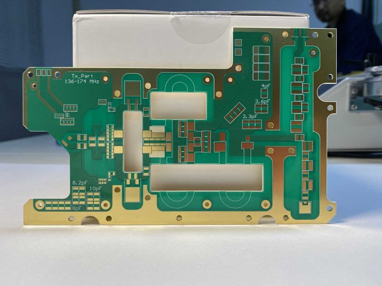
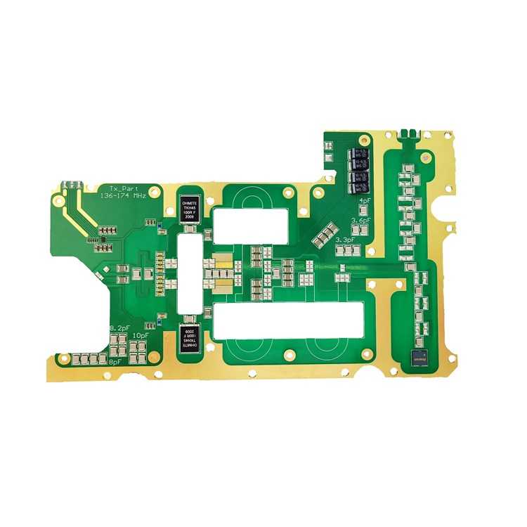
Radio Frequency (RF) Rogers PCB Manufacturer
Radio Frequency PCB, short for RF PCB, is one of the fast-growing PCB technology in recent years, especially in satellite communication systems, military equipment, broadband access, and optical data networks areas. It is defined between 500 MHz and 2 GHz. The prototyping and volume production of RF PCB are two key process after design work is done.

Rogers PCB Example
| Item | Specs |
|---|---|
| Product: | RF PCB |
| Layer: | 4L |
| Material: | RO4350B & FR-4 |
| Finish: | ENIG 2u'' |
| Highlight: | filled & capped vias |

RF PCB Design FAQ
In our experience with RF PCB designers or engineers, the most asked question is “How do I choose the correct laminate for particular project?” Whether out of cost consideration or performance, laminate selection makes a big impact. Below are a few guidelines for refrence:
1.Best Practices of Selecting Material for RF PCB
- Similar Dielectric Constants: In RF PCB design, Non-uniform Dks in substrates may cause performance problems. Working with the PCB fabricator will ensure as close a Dk match as possible.
- Similar Coefficient of Thermal Expansion (CTE): In RF PCB design, differing CTEs of the laminate substrates are likely to cause functional failures and reliability concerns. Therefore when choosing laminates, CTE needs to be ensured similarly.
- Tight Substrate Bonding: How tightly substrate layers bond has a big impact on Dk. Working with the PCB fabricator will help avoid choosing a material set that may negatively impact Dk performance.
- FR-4 Not Recommended: Note that FR-4 doesn’t have the same level of precise dielectric constant and thickness control as specially-formulated RF material. Don’t use it alone for RF applications.
- Smooth Foil Prefered: Due to the skin effect, the smoother copper foil gets, the less resistive losses occur.
1.1 Available Material for RF PCB
| Stock Material for RF PCB | Tg | Td | Dk | Df | CTE-z (Pre-Tg) | Thermal Conductivity |
|---|---|---|---|---|---|---|
| Metric | °C | °C | @10GHz | @10GHz | ppm/°C | W/m*K |
| Rogers RO3003 ceramic-filled PTFE | – | 500° | 3 | 0.0013 | 25 | 0.5 |
Rogers RO4350B High Frequency Circuit | 280° | 390° | 3.5 | 0.0037 | 32 | 0.69 |
| Rogers RO4450F Bondply | >280° | 390° | 3.52 | 0.004 | 50 | 0.65 |
| RT-duroid | – | 500° | 2.2 | 0.0009 | 237 | 0.2 |
| I-Tera MT40 | 200° | 360° | 3.45 | 0.031 | 55 | 0.41 |
| Isola FR408HR | 180° | 360° | 3.67 | 0.012 | 60 | 0.4 |
| Isola I-Speed | 180° | 360° | 3.64 | 0.006 | 60 | 0.6 |
| Astra MT77 | 200° | 360° | 3 | 0.0017 | 50-70 | 0.45 |
RF PCB Capability
| Item | Specs |
|---|---|
| Layers Count: | 2-20 |
| Laminate: | Rogers RO5880, RO5870, RO3003, RO4003C, RO4350B Arlon 25N/25FR, Taconic TLG, ISOLA MT40, ISOLA MT77 |
| Specialty | Controlled impedance, hybrid build, stacked microvias |
| Dielectric thickness | 0 .1mm-30mm |
| Copper weights(finished) | 1/2 to 2 OZ |
| Minimum track and space | 0.075mm/0.075mm |
| Maximum dimensions | 580mm x 1010mm |
| Surface Finishes | HASL, OSP, ENIG, Immersion Tin, Immersion silver |
| Back drilling | ≤16mil |
Get Instant Quote Now
WellCircuits ADVANTAGES
- In-house engineering
- Turnkey FPC & Assembly Solution
- Quick-turn up to 48hrs
- In-house assembly lines
- Support Prototype | Series Production


Reviews
There are no reviews yet.