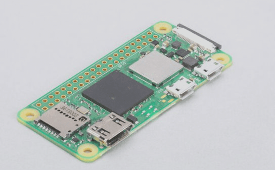
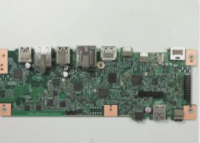
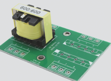
In the PCB solder paste printing process, the PCB printer plays a crucial role in achieving the desired print quality.
During the printing operation, the solder paste is automatically dispensed, and the printing squeegee is pressed onto the stencil, ensuring that the bottom of the stencil contacts the top surface of the circuit board. As the squeegee moves across the entire length of the patterned area, the solder paste is transferred onto the PCB pads through the openings in the stencil. Once the solder paste is deposited, the stencil quickly lifts off the board as the squeegee returns to its starting position. The separation distance, or “lift-off” distance, is determined by the design of the PCB equipment and typically ranges from 0.020″ to 0.040.
The disengagement distance and squeegee pressure are two critical equipment variables that directly impact print quality.
If the stencil does not lift off, the process is referred to as “on-contact” printing. This type of printing is used when an all-metal stencil and squeegee are employed. “Off-contact” printing, on the other hand, is typically used with flexible metal screens.
There are three key factors in solder paste screen printing, often referred to as the “3S”: Solder paste, Stencils, and Squeegees. The proper combination of these three elements is essential for maintaining consistent print quality.
**Squeegee**
The function of the squeegee: During the printing process, the squeegee pushes the solder paste forward, guiding it into the openings of the stencil. It then scrapes off the excess paste, leaving a layer of solder paste on the PCB pads that matches the thickness of the stencil openings.

There are two common types of scrapers: rubber or polyurethane (polyurethane) scrapers and metal scrapers.
The metal squeegee is made from stainless steel or brass, featuring a flat blade shape and operating at a printing angle of 30-55°. When higher pressure is applied, it will not remove solder paste from the openings. Additionally, because they are made of metal, they are more durable than rubber scrapers and do not require frequent sharpening. However, metal scrapers are significantly more expensive and may cause wear to the stencil. In contrast, rubber scrapers typically use a 70-90 durometer hardness. When excessive pressure is applied, the solder paste can penetrate into the bottom of the stencil, potentially creating solder bridges. This requires frequent bottom wiping and can even damage both the scraper and the stencil. Excessive pressure may also cause solder paste to be removed from larger openings, leading to insufficient solder fillets. Low pressure on the squeegee can cause incomplete printing and rough edges. The wear, pressure, and hardness of the squeegee all play a critical role in determining the printing quality and should be carefully monitored. To achieve acceptable printing quality, the edges of the squeegee should remain sharp, straight, and consistent.
**Stencil Type**
The most commonly used stencils today are stainless steel, which are fabricated using three main processes: chemical etching, laser cutting, and electroforming.
Solder paste printed with metal stencils and metal squeegees tends to be applied more heavily, which can sometimes result in an overly thick print. This can be corrected by reducing the stencil thickness.
Additionally, the length and width of the stencil apertures can be reduced by 10% (a process called “fine-tuning”) to reduce the solder paste area on the PCB pad. This adjustment can improve the fit between the stencil and pad, helping to prevent paste leakage between the stencil and the PCB. It can also reduce the “explosion” of solder paste between the bottom of the stencil and the PCB. As a result, the cleaning frequency for the bottom surface of the stencil can be extended from once every 5 to 10 prints to once every 50 prints.
**Solder Paste**
Solder paste consists of a mixture of tin powder and resin. The resin’s primary function is to remove oxides from component leads, pads, and solder beads during the first stage of the reflow process. This stage occurs at 150°C and lasts for approximately three minutes. The solder itself is an alloy of lead, tin, and silver, and reflows at around 220°C during the second stage of the reflow oven.
Viscosity is a critical characteristic of solder paste. Ideally, lower viscosity during the printing process improves the paste’s fluidity, allowing it to flow easily into the stencil openings and onto the PCB pads. After printing, the high viscosity of the solder paste helps it maintain its shape on the pads, preventing collapse.
The typical viscosity range for solder paste is between 500kcps and 1200kcps, with an ideal viscosity of around 800kcps for stencil printing. A practical and cost-effective method for checking the viscosity is as follows:
Stir the solder paste in the container with a spatula for about 30 seconds. Then, scoop up some paste and hold it about three or four inches above the container. Let the paste drip off by itself. It should initially flow down like a thick syrup and then break into small sections as it falls. If the paste does not drip off at all, it is too thick, indicating low viscosity. If it keeps flowing continuously without breaking, it is too thin, indicating low viscosity.
**Control of Printing Process Parameters**
**Snap-off Speed and Distance (Separation between Stencil and PCB)**
After the screen printing process, the PCB is separated from the stencil, leaving the solder paste on the PCB rather than in the stencil holes. For very fine apertures, the solder paste may adhere more readily to the hole walls rather than the pad. The stencil thickness is crucial here. Two factors help in this process: First, the pad area is continuous, and in most cases, the aperture’s inner wall is divided into four sides, which assists in releasing the solder paste. Second, gravity and the adhesive force between the paste and the pad combine to draw the paste into the holes, helping it adhere to the PCB. To maximize this effect, the separation process can be delayed, slowing the PCB’s separation from the stencil. Many machines allow for a delay after printing, and the stroke speed of the worktable’s falling head can be adjusted to be slower than 2-3 mm per second.
**PCB Printing Speed**
The speed at which the squeegee moves across the stencil is critical during the printing process, as solder paste requires time to flow and fill the stencil apertures. If the squeegee moves too quickly, the paste may not have enough time to properly fill the openings, resulting in uneven paste distribution on the pads. At speeds above 20 mm per second, the squeegee may pass over small apertures in just a few milliseconds, leading to insufficient paste deposition.
**PCB Printing Pressure**
The pressure used during PCB printing must be balanced with the hardness of the squeegee. If the pressure is too low, the squeegee will fail to adequately scrape the solder paste from the stencil. On the other hand, excessive pressure or a very soft squeegee can cause the paste to be scraped out of the larger openings in the stencil, leading to insufficient paste deposition.
If you have any PCB manufacturing needs, please do not hesitate to contact me.Contact me
During the printing operation, the solder paste is automatically dispensed, and the printing squeegee is pressed onto the stencil, ensuring that the bottom of the stencil contacts the top surface of the circuit board. As the squeegee moves across the entire length of the patterned area, the solder paste is transferred onto the PCB pads through the openings in the stencil. Once the solder paste is deposited, the stencil quickly lifts off the board as the squeegee returns to its starting position. The separation distance, or “lift-off” distance, is determined by the design of the PCB equipment and typically ranges from 0.020″ to 0.040.
The disengagement distance and squeegee pressure are two critical equipment variables that directly impact print quality.
If the stencil does not lift off, the process is referred to as “on-contact” printing. This type of printing is used when an all-metal stencil and squeegee are employed. “Off-contact” printing, on the other hand, is typically used with flexible metal screens.
There are three key factors in solder paste screen printing, often referred to as the “3S”: Solder paste, Stencils, and Squeegees. The proper combination of these three elements is essential for maintaining consistent print quality.
**Squeegee**
The function of the squeegee: During the printing process, the squeegee pushes the solder paste forward, guiding it into the openings of the stencil. It then scrapes off the excess paste, leaving a layer of solder paste on the PCB pads that matches the thickness of the stencil openings.
There are two common types of scrapers: rubber or polyurethane (polyurethane) scrapers and metal scrapers.
The metal squeegee is made from stainless steel or brass, featuring a flat blade shape and operating at a printing angle of 30-55°. When higher pressure is applied, it will not remove solder paste from the openings. Additionally, because they are made of metal, they are more durable than rubber scrapers and do not require frequent sharpening. However, metal scrapers are significantly more expensive and may cause wear to the stencil. In contrast, rubber scrapers typically use a 70-90 durometer hardness. When excessive pressure is applied, the solder paste can penetrate into the bottom of the stencil, potentially creating solder bridges. This requires frequent bottom wiping and can even damage both the scraper and the stencil. Excessive pressure may also cause solder paste to be removed from larger openings, leading to insufficient solder fillets. Low pressure on the squeegee can cause incomplete printing and rough edges. The wear, pressure, and hardness of the squeegee all play a critical role in determining the printing quality and should be carefully monitored. To achieve acceptable printing quality, the edges of the squeegee should remain sharp, straight, and consistent.
**Stencil Type**
The most commonly used stencils today are stainless steel, which are fabricated using three main processes: chemical etching, laser cutting, and electroforming.
Solder paste printed with metal stencils and metal squeegees tends to be applied more heavily, which can sometimes result in an overly thick print. This can be corrected by reducing the stencil thickness.
Additionally, the length and width of the stencil apertures can be reduced by 10% (a process called “fine-tuning”) to reduce the solder paste area on the PCB pad. This adjustment can improve the fit between the stencil and pad, helping to prevent paste leakage between the stencil and the PCB. It can also reduce the “explosion” of solder paste between the bottom of the stencil and the PCB. As a result, the cleaning frequency for the bottom surface of the stencil can be extended from once every 5 to 10 prints to once every 50 prints.
**Solder Paste**
Solder paste consists of a mixture of tin powder and resin. The resin’s primary function is to remove oxides from component leads, pads, and solder beads during the first stage of the reflow process. This stage occurs at 150°C and lasts for approximately three minutes. The solder itself is an alloy of lead, tin, and silver, and reflows at around 220°C during the second stage of the reflow oven.
Viscosity is a critical characteristic of solder paste. Ideally, lower viscosity during the printing process improves the paste’s fluidity, allowing it to flow easily into the stencil openings and onto the PCB pads. After printing, the high viscosity of the solder paste helps it maintain its shape on the pads, preventing collapse.
The typical viscosity range for solder paste is between 500kcps and 1200kcps, with an ideal viscosity of around 800kcps for stencil printing. A practical and cost-effective method for checking the viscosity is as follows:
Stir the solder paste in the container with a spatula for about 30 seconds. Then, scoop up some paste and hold it about three or four inches above the container. Let the paste drip off by itself. It should initially flow down like a thick syrup and then break into small sections as it falls. If the paste does not drip off at all, it is too thick, indicating low viscosity. If it keeps flowing continuously without breaking, it is too thin, indicating low viscosity.
**Control of Printing Process Parameters**
**Snap-off Speed and Distance (Separation between Stencil and PCB)**
After the screen printing process, the PCB is separated from the stencil, leaving the solder paste on the PCB rather than in the stencil holes. For very fine apertures, the solder paste may adhere more readily to the hole walls rather than the pad. The stencil thickness is crucial here. Two factors help in this process: First, the pad area is continuous, and in most cases, the aperture’s inner wall is divided into four sides, which assists in releasing the solder paste. Second, gravity and the adhesive force between the paste and the pad combine to draw the paste into the holes, helping it adhere to the PCB. To maximize this effect, the separation process can be delayed, slowing the PCB’s separation from the stencil. Many machines allow for a delay after printing, and the stroke speed of the worktable’s falling head can be adjusted to be slower than 2-3 mm per second.
**PCB Printing Speed**
The speed at which the squeegee moves across the stencil is critical during the printing process, as solder paste requires time to flow and fill the stencil apertures. If the squeegee moves too quickly, the paste may not have enough time to properly fill the openings, resulting in uneven paste distribution on the pads. At speeds above 20 mm per second, the squeegee may pass over small apertures in just a few milliseconds, leading to insufficient paste deposition.
**PCB Printing Pressure**
The pressure used during PCB printing must be balanced with the hardness of the squeegee. If the pressure is too low, the squeegee will fail to adequately scrape the solder paste from the stencil. On the other hand, excessive pressure or a very soft squeegee can cause the paste to be scraped out of the larger openings in the stencil, leading to insufficient paste deposition.
If you have any PCB manufacturing needs, please do not hesitate to contact me.Contact me

