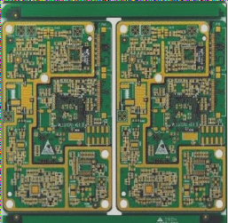
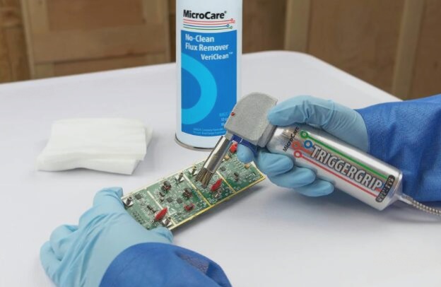
1. In many cases, SMT processing plants often face tight deadlines, especially for rapid prototyping. Customers typically expect quick turnarounds and are reluctant to allow extended time for this process. PCB assembly customers aim to minimize prototyping time as much as possible, thereby reducing overall production cycles. Time saved in the prototyping phase can then be allocated to testing, optimizing strategies, and evaluating production costs.
2. Currently, most products manufactured by PCB assembly plants are large-scale. Consequently, the PCB’s coordinate file can be directly utilized for rapid programming during setup, eliminating the need to individually locate each component’s coordinates. Once the PCB’s coordinate file is acquired, the X and Y axis parameters necessary for the assembly file are already established, requiring only the adjustment of axis parameters specific to the assembly file.

Only familiarity with programming can accelerate the product’s online deployment. The specific steps are as follows:
(1) Export the pick and place files (Generales files) from the PCB design software and transfer them to the industrial computer of the chip mounter.
(2) Navigate to the “Guide” tab, click on “Open Import File”, choose the file transferred to the industrial computer, and click “Open”.
(3) Once opened, ensure that the fields Designator, MidX, MidY, Solation are retained, and rename them to Position, X Coordinate, Y Coordinate, and Angle respectively.
(4) There are two methods to specify MARK1 and MARK2:
– Manually specify MARK: Note down the coordinates of two diagonally opposite points in the PCB design software, enter these coordinates into the MARK and MARK2 fields, click “Generate”, then position the MARK camera to locate MARK, click “Set MARK1 Coordinates”, reposition the MARK camera to locate MARK2, and click “Generate MARK2 Coordinates”.
– System-specified MARK: Upon selection, the PCB system automatically identifies two MARK points from all coordinates. MARK1 appears in green and MARK2 in blue. Click “Generate”, then position the MARK camera to find the green point, click “Set MARK1 coordinates”, move to locate the blue point, and click “Set MARK2 coordinates”.
(5) After MARK2 is set, the interface will automatically switch to the “Installation” tab. Specify the component location and nozzle number, right-click and select “Search component location”, then input the component position number according to the exported BOM form. After clicking “OK”, on the identified blue component, right-click, select “Associate PCB Components”, choose the corresponding PCB components for these mounting positions, right-click again, select “Suction Nozzle Sort”, and choose the nozzles required for these components.
(6) Once all settings are configured, click “Verify Correctly” followed by “Save”.
(7) Ready to operate.
2. Currently, most products manufactured by PCB assembly plants are large-scale. Consequently, the PCB’s coordinate file can be directly utilized for rapid programming during setup, eliminating the need to individually locate each component’s coordinates. Once the PCB’s coordinate file is acquired, the X and Y axis parameters necessary for the assembly file are already established, requiring only the adjustment of axis parameters specific to the assembly file.

Only familiarity with programming can accelerate the product’s online deployment. The specific steps are as follows:
(1) Export the pick and place files (Generales files) from the PCB design software and transfer them to the industrial computer of the chip mounter.
(2) Navigate to the “Guide” tab, click on “Open Import File”, choose the file transferred to the industrial computer, and click “Open”.
(3) Once opened, ensure that the fields Designator, MidX, MidY, Solation are retained, and rename them to Position, X Coordinate, Y Coordinate, and Angle respectively.
(4) There are two methods to specify MARK1 and MARK2:
– Manually specify MARK: Note down the coordinates of two diagonally opposite points in the PCB design software, enter these coordinates into the MARK and MARK2 fields, click “Generate”, then position the MARK camera to locate MARK, click “Set MARK1 Coordinates”, reposition the MARK camera to locate MARK2, and click “Generate MARK2 Coordinates”.
– System-specified MARK: Upon selection, the PCB system automatically identifies two MARK points from all coordinates. MARK1 appears in green and MARK2 in blue. Click “Generate”, then position the MARK camera to find the green point, click “Set MARK1 coordinates”, move to locate the blue point, and click “Set MARK2 coordinates”.
(5) After MARK2 is set, the interface will automatically switch to the “Installation” tab. Specify the component location and nozzle number, right-click and select “Search component location”, then input the component position number according to the exported BOM form. After clicking “OK”, on the identified blue component, right-click, select “Associate PCB Components”, choose the corresponding PCB components for these mounting positions, right-click again, select “Suction Nozzle Sort”, and choose the nozzles required for these components.
(6) Once all settings are configured, click “Verify Correctly” followed by “Save”.
(7) Ready to operate.

