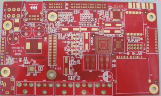
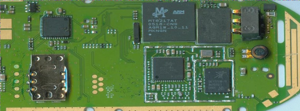
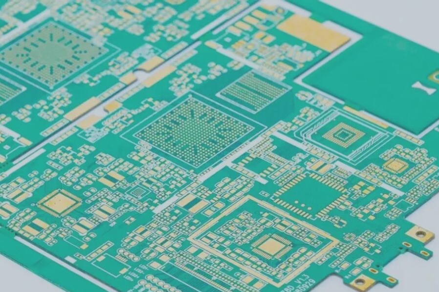
It is imperative for fast PCB board manufacturers to select appropriate typical components as the foundation for organizing the circuit board surface, and the selection must be done sensibly. When placing components on the printed circuit board surface, it is also crucial to consider the routing, shielding, heat dissipation, tidiness of the layout, and assembly process of the printed wires, while also leaving room for installing the shielding structure and heat dissipation structure.
Components that cannot be mounted on the circuit board should be segregated according to the electrical schematic diagram, such as the power switch, band switch, and regulating potentiometer that need to be mounted on the panel, as well as the large and heavy transformer that must be installed on the chassis along with high-power tubes with radiators. There are three methods for connecting the printed circuit board with electrical components other than those mentioned above:
1. Cross-line connection method:
The printed circuit board is directly connected to the external unit (or component) using a wire. In this scenario, the printed wires on the circuit board should have a transfer end.
2. Socket connection method:
A socket on the printed circuit board is connected to the external unit (or component), with one end of the circuit board designed as an insert structure that matches the selected socket.
3. Additional plug and socket connection method:
This method is similar to the socket connection, but one end of the circuit board is mechanically secured with a plug piece (the printed circuit board lacks an insert structure and only has a fixed plug piece mounting hole) which is then connected to the socket. In this case, the printed wires of the circuit board and the relevant conductive parts of the plug piece are soldered together. This structure allows for easy replacement of the inserted part in case of damage.


