Advancements in High-Density PCB Technology
Meeting New Demands with HDI Boards
As electronic products become more high-density and high-precision, new requirements are placed on circuit boards. To increase PCB density effectively, reducing vias and incorporating blind holes is a common method. Professional 32-layer circuit boards exemplify the production of HDI boards.
Benefits of Halogen-Free Materials
- Halogen-free materials have unique properties, with a water absorption performance of 1.1.
- These materials exhibit lower water absorption rates compared to standard epoxy resins, enhancing material reliability, especially in professional 32-layer circuit boards.
Enhancing Material Stability
Improving the stability of materials during the PCB process also enhances their thermal performance. This is crucial for maintaining the integrity of the circuit board.
Dielectric Constant and Insulation Performance
The dielectric constant of materials is influenced by elements such as glass fiber, epoxy resin, and fillers. Halogen-free epoxy resin offers superior electrical insulation compared to halogen-containing epoxy resin, with a dielectric performance rating of 1.3 in a sample 32-layer circuit board.
Optimizing PCB Construction
The process flow for buried and blind via multilayer boards typically involves sequential lamination, ensuring specific design requirements are met for reliable performance.
Importance of Copper Foil Thickness
Thin copper foil is essential for maintaining signal transmission integrity and aiding in heat dissipation under high current conditions. This is crucial for prolonging component life and ensuring optimal performance of digital integrated circuits.
About Dingji Electronics
Dingji Electronics specializes in producing high-quality, high-precision printed circuit boards, including single-sided, double-sided, and multilayer boards. They offer expertise in eight-layer circuit board production.
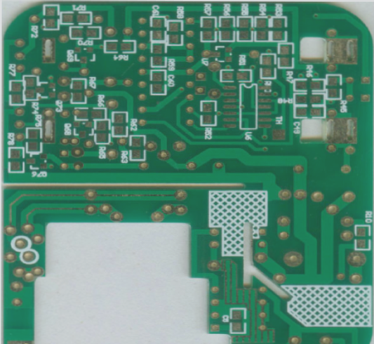
Advanced PCB Layering Techniques
- Multi-layer boards with more than eight layers require precise drilling techniques.
- Blind holes are drilled from the top layer to inner layers, remaining invisible from the surface.
- Buried holes conceal the bottom of inner layer through holes.
- Both blind and buried vias enhance wiring space and design flexibility.
Exploring innovative PCB layering methods can optimize circuit performance and layout efficiency. By utilizing blind and buried vias, designers can achieve compact designs without compromising functionality.

