I have several I2C devices that I typically use with Raspberry Pi computers, where I program them using Python. Recently, I acquired a Raspberry Pi Pico RP2040 microcontroller and decided to try out these I2C devices on the Pico. For programming, I am using Adafruit’s CircuitPython because it offers a wide range of available libraries for various electronic components, making the development process much easier.
As CircuitPython is designed for microcontrollers with limited memory, its libraries are more lightweight compared to the full Python libraries available on desktop computers. For example, popular libraries like NumPy, Matplotlib, SciPy, and Pillow are not available. However, there is a reduced version of NumPy called ulab, which provides similar functionality for basic mathematical operations.
To install CircuitPython on the Raspberry Pi Pico, first, download the .uf2 firmware file from circuitpython.org/downloads. Connect the Pico to your computer while holding down the BOOTSEL button to put it into USB mass storage mode. Then, simply copy the .uf2 file onto the Pico's storage. After disconnecting and reconnecting the Pico, CircuitPython will be ready to use. You can then use Python editors like Thonny or Mu (on a PC or Raspberry Pi) to access the Pico and execute your code. Once you're done, disconnect the Pico from your computer's USB port, and your code will automatically run when it is powered on again.
The key concept in CircuitPython is that your main program is named code.py, which will run automatically when the microcontroller is powered. Any additional libraries can be manually copied to the lib or root folders on the Pico. As soon as you save a file, it will execute, which can be inconvenient during development when you need to stop the program before saving it. While your program can also be named code.txt, main.txt, or main.py, code.py is the default and standard filename. If you want to run a script with a different name, you will need to import it into code.py or main.py for execution. In Thonny, you can run the script directly from the toolbar, but you must stop code.py first. This approach is mainly for testing purposes, as code.py will resume automatically when no other program is running, which can be troublesome when testing new scripts.
Adafruit provides libraries and example files for many sensors and devices, so you should be able to find code examples that will help you get started.
Connecting I2C Devices to the Raspberry Pi Pico
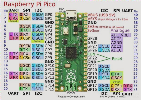
The Raspberry Pi Pico has two I2C peripherals, each with access to 6 sets of GPIO pins. This allows you to connect up to 12 I2C devices without requiring daisy-chaining, unlike the main Raspberry Pi boards, which only provide a single I2C bus by default.
For I2C communication to work on the Pico, you need to include the adafruit_bus_device and adafruit_register libraries in either the lib or root folder of the Pico.
The libraries can be downloaded from circuitpython.org/libraries and then copied to your Pico.
For I2C communication in your program, you will need to import the board and busio libraries. You can initialize the I2C object with the line i2c = busio.I2C(board.SCL, board.SDA), but this doesn't work on the Pico.
On the Pico, you need to manually specify the GPIO pin numbers for SDA and SCL. These pin numbers differ for each microcontroller, so you can use tools from Adafruit's website to identify the correct pin mappings for the I2C bus on your Pico.
Here are some examples of available GPIO pins:
- board.GP0
- board.GP1
- board.GP2
- board.GP3
- board.GP4
- board.GP5
- board.GP6
- board.GP7
- board.GP8
- board.GP9
- board.GP10
- board.GP11
- board.GP12
- board.GP13
- board.GP14
- board.GP15
- board.GP16
- board.GP17
- board.GP18
- board.GP19
- board.GP20
- board.GP21
- board.GP22
- board.GP25 (LED)
- board.A0, board.GP26, board.GP26_A0
- board.A1, board.GP27, board.GP27_A1
- board.A2, board.GP28, board.GP28_A2
For example, if you're using board.GP0 for SDA and board.GP1 for SCL, your I2C initialization would be:
i2c = busio.I2C(board.GP1, board.GP0)
Once the I2C connection is established, you can assign the I2C object to the sensor library. Adafruit's sensor libraries typically come with predefined I2C addresses, but you may need to modify this address based on the actual sensor you are using.
For instance, if Adafruit’s library uses address 0x75 by default, but your sensor is at address 0x76, you can modify the initialization like this:
sensor = adafruit_bme680.Adafruit_BME680_I2C(i2c, address=0x76)
That's the basic process for setting up an I2C connection with the Raspberry Pi Pico using CircuitPython.
Testing I2C Sensors on the Raspberry Pi Pico
This section outlines how to set up and test various I2C sensors on the Raspberry Pi Pico using CircuitPython. The following sensors will be covered:
- VL53L0X - Time of Flight Distance Sensor
- TSL2561 - Ambient Light Sensor
- BME680 - Air Quality, Pressure, Humidity, and Temperature Sensor
- AS7282 - 6-Channel Spectral Sensor
The results from these sensors will be displayed on a 240x240 pixel SPI LCD display.
To use the I2C sensor, you will need the board and busio libraries, as well as the time library for delays. Additionally, you'll need libraries for managing the SPI LCD display: terminalio, displayio, adafruit_st7789, and adafruit_display_text. Since the default font is quite small, we’ll also use the free Sans-SerifPro-Bold font, which requires the adafruit_bitmap_font library. These libraries are available for download from the links at the end of this article.