1. The copper layer of a PCB that is not covered by a solder mask is prone to oxidation when exposed to air.
Both sides of a PCB consist of copper layers. During PCB production, these copper layers typically have a smooth and unprotected surface, regardless of whether they are created using additive or subtractive methods.
While copper’s chemical reactivity is not as high as that of materials like aluminum, iron, or magnesium, pure copper can still easily oxidize when exposed to oxygen in the presence of moisture. Since oxygen and water vapor are present in the air, copper’s surface will quickly undergo an oxidation reaction.
Given the thinness of the copper layer on a PCB, oxidized copper becomes a poor conductor, which can significantly degrade the PCB’s electrical performance.
To prevent oxidation and to distinguish between soldered and non-soldered areas during the soldering process, engineers developed a special protective coating. This coating can be applied to the PCB surface, forming a protective layer that prevents direct contact between copper and air. This protective layer is known as a solder mask, and the material used is referred to as solder mask ink.
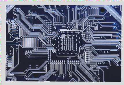
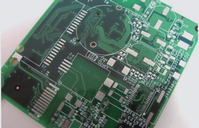
Since this material is referred to as “ink,” it is available in a variety of colors. While the original solder mask could be colorless and transparent, PCBs are often colored for practical reasons, such as aiding maintenance and manufacturing processes.

1. **The transparent solder mask reveals only the PCB background color, which can make the appearance less appealing whether it’s being manufactured, repaired, or sold.** To improve aesthetics, engineers introduced a variety of colors for the solder mask, resulting in black, red, and blue PCBs.
2. **The black PCB makes it difficult to see the traces, which complicates maintenance.**
From this perspective, the color of the PCB doesn’t impact its quality. The difference between black PCBs and other colors like blue or yellow lies solely in the solder mask color.
If the design and manufacturing process of the PCB are identical, the color has no effect on its performance or heat dissipation.
Regarding black PCBs, the traces on the surface layer are almost entirely concealed, making maintenance much more challenging. As a result, black is a color that’s less convenient for manufacturing and use.
Therefore, in recent years, there has been a shift away from black solder masks in favor of dark green, dark brown, and dark blue solder masks, aiming to simplify manufacturing and maintenance.
The argument that “color represents low-end quality” stems from the tendency of manufacturers to use black PCBs for high-end products, while colors like red, blue, green, and yellow are typically associated with lower-end products. Ultimately, it is the product’s color that conveys meaning, not the other way around.
3. **What are the benefits of using precious metals like gold and silver on PCBs?**
Now that we’ve discussed the color, let’s talk about the use of precious metals in PCB manufacturing. Some manufacturers highlight the use of special processes such as gold plating or silver plating when promoting their products. But what purpose do these processes serve?
The PCB surface needs to accommodate soldering components, so part of the copper layer must remain exposed to allow for soldering. These exposed areas are called pads, which are typically small and rectangular or round.
As mentioned earlier, copper on PCBs is prone to oxidation. When the solder mask is applied, any exposed copper pads are left open to the air.
If the copper on the pads oxidizes, it not only makes soldering difficult but also increases the resistivity significantly, which can degrade the product’s performance. To prevent this, engineers use various methods to protect the pads. These include plating the pads with inert metals like gold, applying a thin layer of silver via a chemical process, or covering the copper layer with a special chemical film to prevent direct contact with the air.
For exposed pads, protection is crucial to prevent oxidation and ensure reliable soldering.
Thus, whether gold or silver is used, the primary goal of these processes is to prevent oxidation, protect the pads, and ensure a high yield in the soldering process.
However, using different metals does place certain demands on the PCB’s storage time and conditions. To mitigate this, PCB manufacturers often use vacuum plastic packaging machines to package the PCBs after production and before shipping to customers, ensuring that the boards do not oxidize prematurely.
Before the components are soldered, the PCB manufacturer will also check for any signs of oxidation, removing affected boards to maintain high yield rates. The boards consumers receive have undergone extensive testing, and even with prolonged use, oxidation will typically occur only at the component connection points, with minimal impact on the pads or soldered components.
Since silver and gold have lower resistance, you may wonder: will their use reduce heat generation on the PCB?
The primary factor influencing heat generation is the PCB’s resistance, which is determined by the material of the conductor, as well as the conductor’s cross-sectional area and length. The thickness of the metal layer on the PCB pads is typically less than 0.01 mm. If the pad is processed using an organic protective film (OST) method, there may be no additional thickness at all. The resistance of such a thin layer is nearly zero, making it negligible and not a factor in heat generation.
If you have any PCB manufacturing needs, please do not hesitate to contact me.Contact me
Both sides of a PCB consist of copper layers. During PCB production, these copper layers typically have a smooth and unprotected surface, regardless of whether they are created using additive or subtractive methods.
While copper’s chemical reactivity is not as high as that of materials like aluminum, iron, or magnesium, pure copper can still easily oxidize when exposed to oxygen in the presence of moisture. Since oxygen and water vapor are present in the air, copper’s surface will quickly undergo an oxidation reaction.
Given the thinness of the copper layer on a PCB, oxidized copper becomes a poor conductor, which can significantly degrade the PCB’s electrical performance.
To prevent oxidation and to distinguish between soldered and non-soldered areas during the soldering process, engineers developed a special protective coating. This coating can be applied to the PCB surface, forming a protective layer that prevents direct contact between copper and air. This protective layer is known as a solder mask, and the material used is referred to as solder mask ink.
Since this material is referred to as “ink,” it is available in a variety of colors. While the original solder mask could be colorless and transparent, PCBs are often colored for practical reasons, such as aiding maintenance and manufacturing processes.

1. **The transparent solder mask reveals only the PCB background color, which can make the appearance less appealing whether it’s being manufactured, repaired, or sold.** To improve aesthetics, engineers introduced a variety of colors for the solder mask, resulting in black, red, and blue PCBs.
2. **The black PCB makes it difficult to see the traces, which complicates maintenance.**
From this perspective, the color of the PCB doesn’t impact its quality. The difference between black PCBs and other colors like blue or yellow lies solely in the solder mask color.
If the design and manufacturing process of the PCB are identical, the color has no effect on its performance or heat dissipation.
Regarding black PCBs, the traces on the surface layer are almost entirely concealed, making maintenance much more challenging. As a result, black is a color that’s less convenient for manufacturing and use.
Therefore, in recent years, there has been a shift away from black solder masks in favor of dark green, dark brown, and dark blue solder masks, aiming to simplify manufacturing and maintenance.
The argument that “color represents low-end quality” stems from the tendency of manufacturers to use black PCBs for high-end products, while colors like red, blue, green, and yellow are typically associated with lower-end products. Ultimately, it is the product’s color that conveys meaning, not the other way around.
3. **What are the benefits of using precious metals like gold and silver on PCBs?**
Now that we’ve discussed the color, let’s talk about the use of precious metals in PCB manufacturing. Some manufacturers highlight the use of special processes such as gold plating or silver plating when promoting their products. But what purpose do these processes serve?
The PCB surface needs to accommodate soldering components, so part of the copper layer must remain exposed to allow for soldering. These exposed areas are called pads, which are typically small and rectangular or round.
As mentioned earlier, copper on PCBs is prone to oxidation. When the solder mask is applied, any exposed copper pads are left open to the air.
If the copper on the pads oxidizes, it not only makes soldering difficult but also increases the resistivity significantly, which can degrade the product’s performance. To prevent this, engineers use various methods to protect the pads. These include plating the pads with inert metals like gold, applying a thin layer of silver via a chemical process, or covering the copper layer with a special chemical film to prevent direct contact with the air.
For exposed pads, protection is crucial to prevent oxidation and ensure reliable soldering.
Thus, whether gold or silver is used, the primary goal of these processes is to prevent oxidation, protect the pads, and ensure a high yield in the soldering process.
However, using different metals does place certain demands on the PCB’s storage time and conditions. To mitigate this, PCB manufacturers often use vacuum plastic packaging machines to package the PCBs after production and before shipping to customers, ensuring that the boards do not oxidize prematurely.
Before the components are soldered, the PCB manufacturer will also check for any signs of oxidation, removing affected boards to maintain high yield rates. The boards consumers receive have undergone extensive testing, and even with prolonged use, oxidation will typically occur only at the component connection points, with minimal impact on the pads or soldered components.
Since silver and gold have lower resistance, you may wonder: will their use reduce heat generation on the PCB?
The primary factor influencing heat generation is the PCB’s resistance, which is determined by the material of the conductor, as well as the conductor’s cross-sectional area and length. The thickness of the metal layer on the PCB pads is typically less than 0.01 mm. If the pad is processed using an organic protective film (OST) method, there may be no additional thickness at all. The resistance of such a thin layer is nearly zero, making it negligible and not a factor in heat generation.
If you have any PCB manufacturing needs, please do not hesitate to contact me.Contact me


