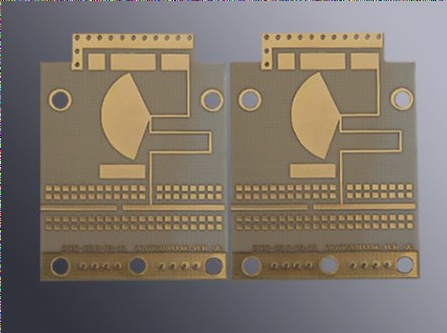
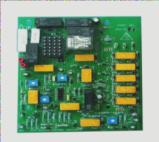
1. The through-hole solder paste is used to print solder paste directly onto the Plating Through Hole of an FR4 PCB. This allows for the traditional plug-in/DIP insert parts to be inserted directly into the electroplated through-hole that has been printed with solder paste.
2. At this point, most of the solder paste on the electroplated through-hole will adhere to the solder pins of the plug-in parts. These solder pastes will melt again in the high temperature of the reflow furnace, welding the parts onto the circuit board.
3. This method goes by several names, including pin-in-paste, invasive reflow soldering, ROT, and reflow of through-hole.
4. The advantage of this method is that it eliminates the need for hand soldering or wave soldering, thereby saving labor hours. Additionally, it can improve the quality of the weld and reduce the possibility of solder short circuits.

However, this method has the following inherent limitations:
1. The heat resistance of traditional parts must meet the temperature requirements of reflow soldering, which may use materials with lower temperature resistance than reflow parts for general plug-in parts. The process of reflow welding traditional parts and ordinary SMT parts together requires temperature resistance of reflow. Lead-free parts can now withstand 260 ° C+10sec and should have a tape-on-reel and sufficient plane to be placed on the fr4 pcb through the SMT pick and place machine. Otherwise, an additional operator may need to manually place the parts, leading to increased working hours and unstable quality due to the possibility of interference with other parts.
2. The solder pad between the part body and PCB must have a standoff design to prevent the molten solder paste from traveling along the gap between the part and the PCB during Reflow. Lack of standoff may lead to electrical quality issues in the future.
3. Making parts on the second side of traditional parts is preferable to avoid the risk of solder paste flowing back into the traditional part and causing internal short circuit, especially for connector parts.
4. Ensuring the right amount of solder is the biggest challenge. Methods for increasing solder amount include reserving enough space for overprint near the through hole, reducing the diameter of the through hole, using step-up or step-down or stencil steel plates, adjusting the appropriate solder paste, speed, pressure, and using manual dispensing if necessary.
5. The actual insertion function of the whole circuit board needs to be tested. A complete machine product is composed of more than one circuit board, and the real insertion involves assembling all the circuit boards and parts needed for a complete machine to test its functions. It is important to prepare a set of circuit boards with normal functions as standard templates. Using extended wiring for testing can be advantageous in terms of easy assembly and cost-effectiveness, especially for small production quantities or when the fr4 pcb design has not been finalized in the EVT stage. However, it may also pose the risk of damaging the standard template and can be time-consuming.
2. At this point, most of the solder paste on the electroplated through-hole will adhere to the solder pins of the plug-in parts. These solder pastes will melt again in the high temperature of the reflow furnace, welding the parts onto the circuit board.
3. This method goes by several names, including pin-in-paste, invasive reflow soldering, ROT, and reflow of through-hole.
4. The advantage of this method is that it eliminates the need for hand soldering or wave soldering, thereby saving labor hours. Additionally, it can improve the quality of the weld and reduce the possibility of solder short circuits.

However, this method has the following inherent limitations:
1. The heat resistance of traditional parts must meet the temperature requirements of reflow soldering, which may use materials with lower temperature resistance than reflow parts for general plug-in parts. The process of reflow welding traditional parts and ordinary SMT parts together requires temperature resistance of reflow. Lead-free parts can now withstand 260 ° C+10sec and should have a tape-on-reel and sufficient plane to be placed on the fr4 pcb through the SMT pick and place machine. Otherwise, an additional operator may need to manually place the parts, leading to increased working hours and unstable quality due to the possibility of interference with other parts.
2. The solder pad between the part body and PCB must have a standoff design to prevent the molten solder paste from traveling along the gap between the part and the PCB during Reflow. Lack of standoff may lead to electrical quality issues in the future.
3. Making parts on the second side of traditional parts is preferable to avoid the risk of solder paste flowing back into the traditional part and causing internal short circuit, especially for connector parts.
4. Ensuring the right amount of solder is the biggest challenge. Methods for increasing solder amount include reserving enough space for overprint near the through hole, reducing the diameter of the through hole, using step-up or step-down or stencil steel plates, adjusting the appropriate solder paste, speed, pressure, and using manual dispensing if necessary.
5. The actual insertion function of the whole circuit board needs to be tested. A complete machine product is composed of more than one circuit board, and the real insertion involves assembling all the circuit boards and parts needed for a complete machine to test its functions. It is important to prepare a set of circuit boards with normal functions as standard templates. Using extended wiring for testing can be advantageous in terms of easy assembly and cost-effectiveness, especially for small production quantities or when the fr4 pcb design has not been finalized in the EVT stage. However, it may also pose the risk of damaging the standard template and can be time-consuming.


