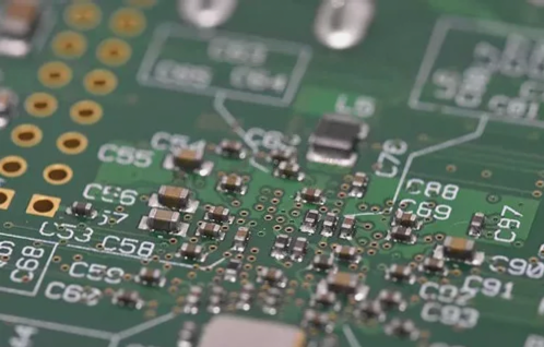
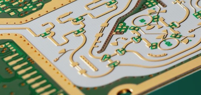
1. The flexible circuit board can be freely bent, wound, and folded. It is constructed using a polyimide film base material. The board undergoes different processes depending on the number of layers, categorized into double-sided flexible circuit boards and multilayer flexible circuit boards.
2. FPCs (Flexible Printed Circuits) can endure millions of dynamic bends without damaging the wires. They offer the flexibility to be arranged according to spatial layout requirements, seamlessly moving and expanding in three-dimensional space. This facilitates the integration of component assembly and wire connection.
3. Flexible circuit boards significantly reduce the volume and weight of electronic products, aligning with the modern trend in electronics towards high density, miniaturization, and high reliability.
4. The structure of a flexible circuit board is determined by the number of layers of conductive copper foil, leading to its classification into single-layer flex PCBs, double-layer flex PCBs, and multilayer flex PCBs.

(1) Substrate: The material is polyimide (POLYMIDE), a high-temperature resistant, high-strength polymer. It can endure temperatures of up to 400 degrees Celsius for 10 seconds, with a tensile strength ranging from 15,000 to 30,000 PSI. The 25μm thick substrate is the most cost-effective and commonly used. For greater rigidity, a 50μm substrate is recommended. Conversely, for a softer circuit board, a 13μm substrate is preferred.
(2) Scotch tape: Available in epoxy resin and polyethylene variants, both are thermosetting adhesives. Polyethylene has lower strength. Opt for polyethylene for a softer circuit board. Thicker substrates and the transparent adhesive on them result in a harder board. When the circuit board has significant bending areas, opt for thinner substrates and transparent adhesive to reduce stress on the copper foil surface, minimizing the risk of microcracks. Single-layer boards should be favored for such areas where possible.
(3) Copper foil: It comes in rolled copper and electrolytic copper types. Rolled copper boasts high strength and bend resistance but comes at a higher cost. Electrolytic copper is more economical but lacks strength, suitable for occasions with minimal bending. The choice of copper foil thickness depends on the minimum lead width and spacing. Thinner copper foil allows for smaller minimum achievable width and spacing. When selecting rolled copper, ensure the rolling direction aligns with the main bending direction of the circuit board.
(4) Protective film and its scotch tape: A 25μm protective film increases circuit board hardness at a lower cost. For boards with significant bends, a 13μm protective film is preferable. Transparent adhesive is also available in epoxy resin and polyethylene variants, with epoxy resin yielding a harder board. After hot pressing, excess transparent adhesive may extrude from the protective film edges. If pad size exceeds the opening size of the protective film, extruded adhesive may irregularize pad edges. In such cases, opt for 13μm thick transparent adhesive whenever possible.
(5) Pad plating: For boards with large bends and exposed pads, electroplated nickel + electroless gold layering is recommended. The nickel layer should be minimal, ideally 0.5-2μm, while the chemical gold layer should range from 0.05-0.1μm.
2. FPCs (Flexible Printed Circuits) can endure millions of dynamic bends without damaging the wires. They offer the flexibility to be arranged according to spatial layout requirements, seamlessly moving and expanding in three-dimensional space. This facilitates the integration of component assembly and wire connection.
3. Flexible circuit boards significantly reduce the volume and weight of electronic products, aligning with the modern trend in electronics towards high density, miniaturization, and high reliability.
4. The structure of a flexible circuit board is determined by the number of layers of conductive copper foil, leading to its classification into single-layer flex PCBs, double-layer flex PCBs, and multilayer flex PCBs.

(1) Substrate: The material is polyimide (POLYMIDE), a high-temperature resistant, high-strength polymer. It can endure temperatures of up to 400 degrees Celsius for 10 seconds, with a tensile strength ranging from 15,000 to 30,000 PSI. The 25μm thick substrate is the most cost-effective and commonly used. For greater rigidity, a 50μm substrate is recommended. Conversely, for a softer circuit board, a 13μm substrate is preferred.
(2) Scotch tape: Available in epoxy resin and polyethylene variants, both are thermosetting adhesives. Polyethylene has lower strength. Opt for polyethylene for a softer circuit board. Thicker substrates and the transparent adhesive on them result in a harder board. When the circuit board has significant bending areas, opt for thinner substrates and transparent adhesive to reduce stress on the copper foil surface, minimizing the risk of microcracks. Single-layer boards should be favored for such areas where possible.
(3) Copper foil: It comes in rolled copper and electrolytic copper types. Rolled copper boasts high strength and bend resistance but comes at a higher cost. Electrolytic copper is more economical but lacks strength, suitable for occasions with minimal bending. The choice of copper foil thickness depends on the minimum lead width and spacing. Thinner copper foil allows for smaller minimum achievable width and spacing. When selecting rolled copper, ensure the rolling direction aligns with the main bending direction of the circuit board.
(4) Protective film and its scotch tape: A 25μm protective film increases circuit board hardness at a lower cost. For boards with significant bends, a 13μm protective film is preferable. Transparent adhesive is also available in epoxy resin and polyethylene variants, with epoxy resin yielding a harder board. After hot pressing, excess transparent adhesive may extrude from the protective film edges. If pad size exceeds the opening size of the protective film, extruded adhesive may irregularize pad edges. In such cases, opt for 13μm thick transparent adhesive whenever possible.
(5) Pad plating: For boards with large bends and exposed pads, electroplated nickel + electroless gold layering is recommended. The nickel layer should be minimal, ideally 0.5-2μm, while the chemical gold layer should range from 0.05-0.1μm.


