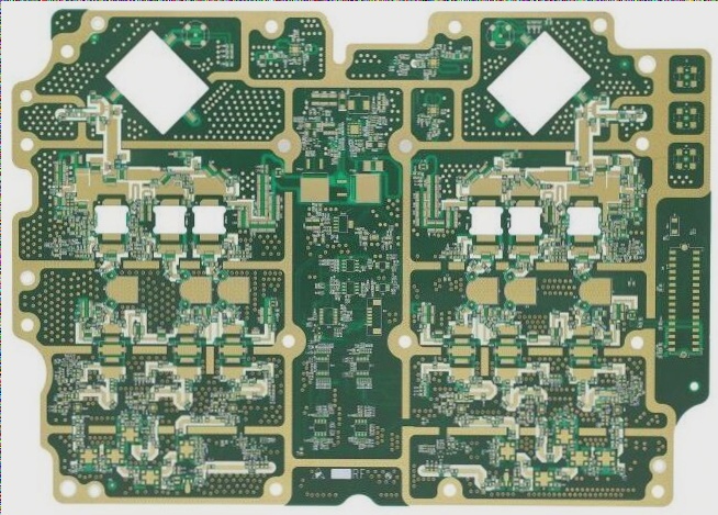
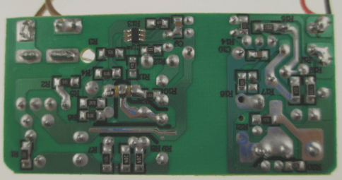
1. For the selection of a substitute Microwave PCB Circuit Board, dielectric properties should be prioritized. Additionally, factors such as the type and thickness of copper foil on its surface, environmental adaptability, processability, and cost must be considered.
2. There are two types of copper foil available for Microwave PCB Circuit Boards: 35 μm and 18 μm. Thinner copper foils, like 18 μm, enable higher graphic precision. Opting for 35 μm copper foil compromises processability due to reduced graphic accuracy, leading to higher rates of product defects. WellCircuits, drawing from its Microwave PCB manufacturing experience, suggests that the type of copper foil also impacts graphic accuracy. Currently, calendered copper foil is preferable over electrolytic copper foil for achieving high precision.
3. The selection of Microwave PCB Circuit Board substitutes involves careful consideration of machinability. With evolving design demands, some substrates incorporate aluminum liners. While these enhance performance, they complicate graphic and contour processing, lengthening production cycles. Therefore, substrates with aluminum liners should be avoided where feasible.
4. Rogers’ TMM series microwave substrates, composed of thermosetting resin filled with ceramic powder, vary in performance. TMM10, densely filled with ceramic powder, poses challenges in pattern and contour processing, prone to damage and internal cracks, thereby reducing yield. Laser cutting is currently used for TMM10 shaping, despite its high cost and prolonged production cycles. Hence, where feasible, Rogers’ RT/Duroid series substrates meeting dielectric performance requirements are preferred.
5. Environmental adaptability is critical for Microwave PCB Circuit Board substitutes. Existing microwave substrates typically meet the required ambient temperature range of -55 ℃ to +125 ℃. However, other environmental factors should also be considered,
This revision aims to enhance clarity and readability while maintaining the technical details essential for PCB specialists.

1. Influence of Porosity on Substrate Selection: For microwave PCBs requiring through-hole metallization, a substrate with a smaller Z-axis thermal expansion coefficient should be chosen to minimize the risk of metallized hole fractures under varying temperatures. This consideration is crucial alongside meeting dielectric requirements.
2. Influence of Humidity on Base Material Selection: Although the base material resin itself exhibits minimal water absorption, the addition of reinforcement materials increases overall water absorption. This heightened absorption can adversely affect dielectric properties in high humidity environments. Therefore, selecting base materials with low water absorption or implementing protective structural and technological measures is advisable.
The structural complexity of microwave PCBs necessitates stringent dimensional accuracy requirements. Given the large production quantities of identical varieties, NC milling technology is indispensable. Hence, microwave PCB design should fully integrate the characteristics of numerical control processing, ensuring that all internal corners are rounded to facilitate seamless processing and formation.
Designing microwave boards should balance precision requirements, acknowledging the significant dimensional deformation tendencies of non-metallic materials. It’s impractical to demand the same processing accuracy as for metal parts. Precision concerns primarily arise from deviations in profile processing affecting microstrip line lengths and thereby microwave performance. Ideally, a 0.2mm gap between the microstrip line’s end and the plate edge mitigates the impact of profile processing deviations.
The manufacturing of microwave PCBs differs substantially from that of standard single, double-sided, and multilayer boards. It serves not only as structural support and connectors but also as vital signal transmission lines. Various factors, including layer count, material characteristics, metallized hole requirements, surface coating methods, circuit design specifics, manufacturing line accuracy, equipment advancement, and chemical solutions, constrain microwave manufacturing processes. Each process is tailored to specific requirements; for instance, circuit nickel-gold electroplating may involve positive or negative plate processes depending on the application.
Microwave PCB manufacturing is advancing towards more rigorous processing akin to FR-4 rigid PCBs. This evolution is evident in multilayer configurations, enhanced circuit accuracy, three-dimensional CNC machining capabilities, and diversified surface coating techniques. As the variety of substrate types and design demands continues to expand, ongoing optimization of microwave PCB manufacturing processes is essential for meeting evolving industry standards and demands.

