Signal Return and Cross-Segmentation in High-Speed PCB Boards
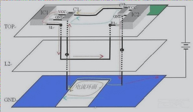
When dealing with high-speed PCB boards, understanding signal return and cross-segmentation is crucial. In this simplified scenario, we delve into ground return, power return, and various cross-segmentation issues. The diagram below illustrates the setup:
Ground and Power Connections
In the diagram, IC1 serves as the signal output terminal, while IC2 acts as the signal input terminal. Both IC1 and IC2 are grounded through the third layer, which functions as the ground layer. The top layer in the upper right corner represents the power plane, connecting to the positive pole of the power supply. Decoupling capacitors C1 and C2 are in place for IC1 and IC2, respectively.
At low frequencies, the current loop flows from the power supply to IC1, through the signal path, and back to the power supply via the ground layer. However, at high frequencies, signal distribution characteristics on the PCB come into play, impacting ground return and signal integrity.
High-frequency signals can induce reverse currents in nearby conductors, leading to energy radiation and potential signal coupling with external sources. To mitigate these effects, proper decoupling capacitors close to the chips are essential.
Crosstalk and Clock Signals
When dealing with clock signals and data lines in parallel, maintaining a consistent current return path is vital. Simultaneous switching of data lines in the same direction can induce reverse currents on the clock line, leading to crosstalk issues that affect signal integrity.
The magnitude of crosstalk is not solely determined by the interference source’s level but also by the rate of change of current. Careful consideration of edge cases is necessary, as even low-speed signals can exhibit significant crosstalk, challenging common assumptions about interference levels.
Signals and Return Paths in PCB Design
- Signals with steep edges contain harmonic components, affecting amplitude at frequency multiplication points.
- Choosing chips based solely on fast switching speeds can increase costs and worsen crosstalk and EMC problems.
- Adjacent power planes or capacitors across signals can act as return paths to ground, reducing reactance.
- Transceiver chip IO power supplies often share connections with 0.01-0.1uF decoupling capacitors to enhance return flow.
- Using alternative power planes for return paths without low-reactance connections to ground can lead to longer return paths and crosstalk effects.
- High-pass filters, like a 10-ohm resistor in series with a 680p capacitor, can help manage cross-power splitting situations by isolating low-frequency crosstalk.
- Adding small capacitors to ground at signal ends can aid in creating return paths, though space constraints may pose challenges.