Abstract: This article introduces the design principles of a simple tool for removing the edge of PCBA boards. The tool efficiently cuts PCB boards of various sizes pre-engraved with V-shaped grooves, aiming to assist engineering designers in their work.
1. Development background:
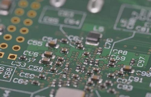
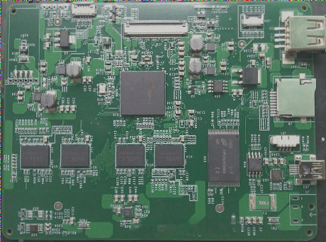
PCBA (Printed Circuit Board Assembly) refers to a printed circuit board that has undergone component assembly and finds wide application across aviation, numerical control, computer, and automation equipment sectors. Manufacturing and logistical requirements necessitate leaving a process edge on PCBA boards to facilitate handling. This edge, however, is unnecessary for the final product and thus needs removal after component assembly. Methods for removing the process edge of PCBA boards generally fall into three categories: V-cut splitters, milling splitters, and manual methods.
For instance, milling splitters, also known as contour cutters, enhance quality by surpassing the linear limitations of V-cutters. These high-speed devices follow pre-programmed paths to separate multi-piece PCBAs, mitigating issues like manual breaking or V-cutting defects and thereby improving product quality while reducing scrap. However, their complexity and cost (programming required) present drawbacks. Conversely, V-cut splitters are more economical but limited to straight-line cutting along the V-groove of PCBA boards, with higher costs associated with blade consumables.
Manual removal involves breaking by hand or using tools like needle-nose pliers. It offers cost-effectiveness and convenience but risks generating stress and causing component damage. This method suits small-batch, multi-variety, and low-cost manufacturing needs, yet exacerbates batch, cost, and reliability concerns.
To address these challenges, we have developed a straightforward tool for manual PCBA board edge removal. This tool tackles these issues, alleviating associated contradictions to a significant extent.

2. Tooling Design Scheme
This tooling achieves the purpose of removing the process edge through a simple mechanical structure, thus keeping costs low. It features a series of adjustable structures to accommodate varying sizes and thicknesses of PCBA boards, reducing mechanical stress during edge removal to enhance work quality. Consequently, this tooling meets requirements for variety, cost-effectiveness, and high quality in process edge removal, making it a practical, convenient, and affordable auxiliary device.
The tooling adopts the following technical scheme: an adjustable auxiliary device for manually removing the process edge of the PCBA board, consisting of an installation bottom plate, a slider base, a movable slider, an adjustment button, and a transmission structure. By manually adjusting the adjustment button, the movable slider moves along a predetermined track on the slider base via the transmission structure. Once positioned correctly, place the PCBA board’s process edge into the device’s slot and secure the board’s bottom with both hands. Gently applying force in one direction facilitates the manual removal of the process edge, as illustrated in Figure 3. Note that force should not be applied to the PCBA’s upper part with both hands, as this may cause damage.
The installation base plate of the tooling can be a workbench or other forms, not limited to a base plate. The movable fit and structural form can vary, and the adjustment button may employ manual rotation or other forms. Similarly, the transmission structure can include cone gear transmission or other variations, offering flexibility beyond typical designs.
Compared with existing methods, the tooling offers several advantages: (1) Low production cost; (2) Ease of operation; (3) High quality edge removal with minimal stress on PCBA components; (4) Versatility to accommodate different PCBA thicknesses and margins; (5) Flexible structure allowing manual adjustment for various PCBA sizes.
3. Conclusion
The application of this manual auxiliary device for process edge removal on PCBA boards not only ensures controlled stress levels but also effectively manages production costs. By replacing high-cost specialized equipment, this practical, convenient, flexible, and adaptable tooling significantly reduces overall expenses. Its broad applicability in PCBA process edge removal establishes it as a reliable solution for diverse industry needs.
1. Development background:
PCBA (Printed Circuit Board Assembly) refers to a printed circuit board that has undergone component assembly and finds wide application across aviation, numerical control, computer, and automation equipment sectors. Manufacturing and logistical requirements necessitate leaving a process edge on PCBA boards to facilitate handling. This edge, however, is unnecessary for the final product and thus needs removal after component assembly. Methods for removing the process edge of PCBA boards generally fall into three categories: V-cut splitters, milling splitters, and manual methods.
For instance, milling splitters, also known as contour cutters, enhance quality by surpassing the linear limitations of V-cutters. These high-speed devices follow pre-programmed paths to separate multi-piece PCBAs, mitigating issues like manual breaking or V-cutting defects and thereby improving product quality while reducing scrap. However, their complexity and cost (programming required) present drawbacks. Conversely, V-cut splitters are more economical but limited to straight-line cutting along the V-groove of PCBA boards, with higher costs associated with blade consumables.
Manual removal involves breaking by hand or using tools like needle-nose pliers. It offers cost-effectiveness and convenience but risks generating stress and causing component damage. This method suits small-batch, multi-variety, and low-cost manufacturing needs, yet exacerbates batch, cost, and reliability concerns.
To address these challenges, we have developed a straightforward tool for manual PCBA board edge removal. This tool tackles these issues, alleviating associated contradictions to a significant extent.

2. Tooling Design Scheme
This tooling achieves the purpose of removing the process edge through a simple mechanical structure, thus keeping costs low. It features a series of adjustable structures to accommodate varying sizes and thicknesses of PCBA boards, reducing mechanical stress during edge removal to enhance work quality. Consequently, this tooling meets requirements for variety, cost-effectiveness, and high quality in process edge removal, making it a practical, convenient, and affordable auxiliary device.
The tooling adopts the following technical scheme: an adjustable auxiliary device for manually removing the process edge of the PCBA board, consisting of an installation bottom plate, a slider base, a movable slider, an adjustment button, and a transmission structure. By manually adjusting the adjustment button, the movable slider moves along a predetermined track on the slider base via the transmission structure. Once positioned correctly, place the PCBA board’s process edge into the device’s slot and secure the board’s bottom with both hands. Gently applying force in one direction facilitates the manual removal of the process edge, as illustrated in Figure 3. Note that force should not be applied to the PCBA’s upper part with both hands, as this may cause damage.
The installation base plate of the tooling can be a workbench or other forms, not limited to a base plate. The movable fit and structural form can vary, and the adjustment button may employ manual rotation or other forms. Similarly, the transmission structure can include cone gear transmission or other variations, offering flexibility beyond typical designs.
Compared with existing methods, the tooling offers several advantages: (1) Low production cost; (2) Ease of operation; (3) High quality edge removal with minimal stress on PCBA components; (4) Versatility to accommodate different PCBA thicknesses and margins; (5) Flexible structure allowing manual adjustment for various PCBA sizes.
3. Conclusion
The application of this manual auxiliary device for process edge removal on PCBA boards not only ensures controlled stress levels but also effectively manages production costs. By replacing high-cost specialized equipment, this practical, convenient, flexible, and adaptable tooling significantly reduces overall expenses. Its broad applicability in PCBA process edge removal establishes it as a reliable solution for diverse industry needs.


