The Importance of Silkscreen Layer in PCB Design
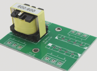
The silkscreen layer of a PCB board plays a vital role in guiding circuit installation and maintenance by providing essential information through logos, patterns, and text codes on the board’s surfaces.
Key Guidelines for Silkscreen Placement:
- Components should be placed in only two directions to avoid visual fatigue.
- Avoid placing vias on the silkscreen whenever possible.
- Avoid pressing silkscreen on high-speed signal lines to maintain signal quality.
- Ensure consistent reading direction for easy soldering and component identification.
- Clearly mark pin numbers and connectors for easy assembly.
- Match silkscreen size with specially packaged components for alignment.
- Add markings near mounting holes for easy installation.
- Address ambiguity with clear markings like signal flow directions.
Best Practices for Silkscreen Layout:
- Label all components and holes clearly for easy identification.
- Avoid placing silkscreen on solder pads or tin baths.
- Mark polarity of components for quick reference.
- Ensure accuracy of PCB photo files and component identifiers.
- Indicate directional connectors clearly.
- Include barcode and essential information on the PCB documents.
Following these guidelines ensures that the silkscreen layer on a PCB board is optimized for functionality, clarity, and ease of use during the circuit’s lifecycle.