Building a Compact Stereo Digital FM Transmitter Circuit
FM transmitters and receivers are popular in electronics projects, but creating a digital FM transmitter can be a challenge. This project introduces a compact stereo digital FM transmitter circuit operating in the 87MHz to 108MHz frequency range. The circuit, controlled by an ATMega8 microcontroller, features a 0.96-inch SPI OLED display and a KT0803L FM transmitter chip for clear audio reception.
Key Features:
- Frequency adjustable in 0.1MHz steps
- Connects to audio sources like phones or computers
- Microphone or AUX cable input for preferred audio broadcasting
If you’re interested in trying this project, download the Gerber files or order high-quality PCB boards for just $5. Additionally, fully assembled PCBs are available for purchase with free shipping.
Specifications:
- Input Voltage: 7-9VDC
- Current Consumption: 50mA
- Frequency Range: 87MHz to 108MHz
- Frequency Step Size: 0.1MHz
- AUX Input: Stereo
Circuit Analysis:
Figure 1 displays the schematic diagram of the digital FM transmitter project, covering the 87MHz to 108MHz range. Let’s delve into the components:
A-1: Power Supply
The board’s power is supplied via the XH connector P2, with an input voltage range of 7V to 9V DC. Various components like FB1, C11, REG2, C12, C13, REG1, D1, C10, and C14 ensure stable and noise-free power delivery.
A-2: Microphone Input
Connect an electret microphone to the board using the XH connector P1. Components like C8, R6, C9, and Q1 amplify and filter the microphone signal for transmission.
A-3: Logic Level Converter
Utilizing 2N7002 N-Channel MOSFETs, resistors, and the microcontroller, this section converts logic levels for proper communication between components.
A-4: FM Transmitter
The KT0803L chip, SMD headphone jack, capacitors, and antenna connector form the core of the FM transmission section, enabling audio transmission from various devices.
A-5: Microcontroller and Display
The ATMega8-AU microcontroller, OLED display, pushbuttons, and supporting components create the central control and user interface for the circuit, allowing for frequency adjustments and stable operation.
The Latest in PCB Technology
Introducing the 0.96-inch 128×64 Yellow-Blue SPI OLED Display, a cutting-edge display for your PCB projects.
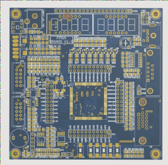
PCB Layout
Explore the two-layer board layout with most components in SMD packages for enhanced efficiency and performance. Check out the PCB layout of the digital FM transmitter project below:

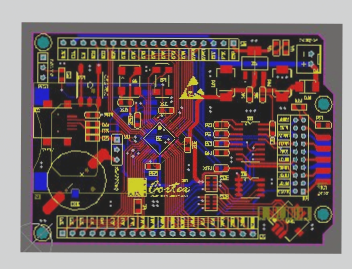
Board Assembly Drawings
Get a closer look at the board assembly drawings of the digital FM transmitter project to streamline your assembly process:

Code and Programming Tips
For those looking to replicate the project, download the HEX file and program the microcontroller with the provided instructions. Remember to set the MCU Clock Fuse Bits to 8MHz (Internal).
If customization is on your mind, find the MCU code for the Arduino platform below. Make sure to have the FM library, SPI OLED library, and MiniCore board manager library installed in your Arduino IDE. Don’t forget to set the clock source to Internal, 8MHz.
#include <FMTX.h>
#include <SPI.h>
#include "SSD1306Ascii.h"
#include "SSD1306AsciiSpi.h"
#define CS_PIN 7
#define RST_PIN 9
#define DC_PIN 8
#define Down_Key 15