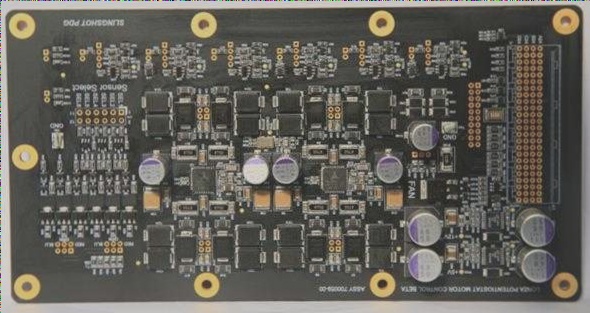
Best Practices for PCB Component Positioning
1. When placing components that require frequent adjustment or replacement, consider the overall structural requirements of the machine. Components like potentiometers, inductance coils, and switches should be positioned with easy access in mind.
2. Position components on the printed circuit board for easy adjustment and replacement. Ensure that components adjusted outside the machine align with adjustment knobs on the chassis panel to avoid spatial conflicts.
3. Match panel openings with switches and vacant positions on the circuit board. Provide fixing holes near terminals and plug-in parts to accommodate thermal expansion.
4. Add margins for components with large tolerances. For example, electrolytic capacitors should have a margin of at least 1mm, while transformers and resistors exceeding 5W should have a margin of at least 3mm.
5. Maintain a minimum distance of 10mm between electrolytic capacitors and heat-generating components to prevent thermal issues. Keep a distance of 20mm between other components and radiators to avoid interference.
6. Avoid placing stress-sensitive components in high-stress areas of the circuit board. Ensure that the component layout meets soldering spacing requirements to reduce shadowing effects during soldering.
7. Reserve positioning holes and brackets on the circuit board to prevent bending during the soldering process. Leave a 5~10mm gap in large-area boards to maintain structural integrity.

