Designing PCBs with Non-Standard Shapes
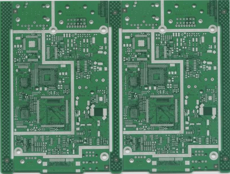
- Most PCBs are rectangular, but some projects require irregular shapes, posing design challenges.
- As PCB sizes shrink and functionalities expand, managing complex circuit board designs becomes crucial.
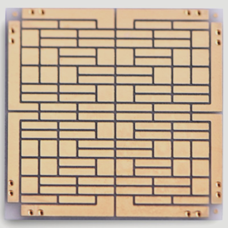
- Creating simple PCB shapes is easy, but complex enclosures with height constraints can be a challenge.
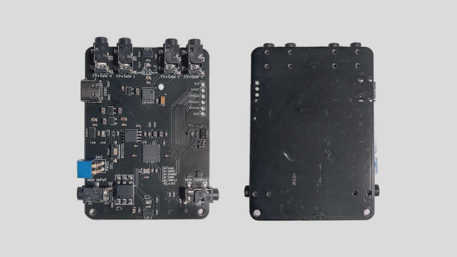
- Reconstructing information in EDA tools for non-standard shapes can be time-consuming.
- Integration of multiple functions into non-rectangular packages is a trend in consumer electronics.
Integrating Mechanical Engineering Standards into PCB Design
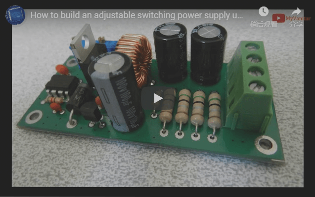
- Rigid and flexible circuit boards play a vital role in devices like handheld scanners and thermal printers.
- Reusing data from mechanical drawings in PCB design tools can minimize redundant efforts.
- Using formats like DXFIDF and ProStep can streamline the input of mechanical information into PCB layout software.
- DXF format bridges mechanical and PCB design sectors, facilitating QR data exchange.
- 3D capabilities in PCB tools have led to the emergence of the IDF format for exchanging circuit board and component information.
Benefits and Challenges of IDF Format
- IDF format specifies component quantities and locations in 3D, enhancing PCB representation.
- IDF files can include information on restricted areas and component heights, aiding in 3D visualization.
- Relocating components or modifying the circuit board shape can result in a new IDF file.
- Large IDF file sizes may lead to time-consuming re-introduction of components when making changes.
- Creating custom identifiers in IDF files can help track specific modifications on larger circuit boards.
This content provides insights into designing PCBs with non-standard shapes, integrating mechanical engineering standards into PCB design, and the benefits and challenges of using the IDF format for exchanging circuit board information.
To Enhance 3D Data Transmission
Designers are constantly looking for ways to improve 3D data transmission. One key focus is on enhancing the STEP format, which provides detailed information on circuit board dimensions and component layouts.
STEP Component Model
The STEP component model offers a detailed 3D description of components, allowing for the seamless transfer of data between PCBs and machinery. However, there is currently a lack of mechanism to track changes.
Introducing ProStep Format
The ProStep format was introduced to address the need for improved STEP file exchanges. This format not only transfers data similar to IDF and STEP but also enables tracking changes and reviewing modifications post baseline establishment.
ECO Process for Modifications
PCB and mechanical engineers can now collaborate on approving modifications to circuit board shapes, suggesting alternative sizes, and repositioning components through the innovative ECO (Project Change Order) process between ECAD and the Machinery Group.
Benefits of Professional STEP Formats
Most ECAD and mechanical CAD systems now support professional STEP formats, facilitating better communication and significantly reducing time and costs associated with complex electromechanical designs.
Efficiency in Designing Circuit Board Shapes
Engineers can now create intricate circuit board shapes and transmit them electronically, eliminating any confusion regarding dimensions and ultimately saving time in the design process.
Consider Utilizing Advanced Formats
If you have not yet explored the applications of DXFIDF, STEP, or ProStep formats for information exchange, it is worth considering. Leveraging electronic data exchange can help prevent time wastage in designing complex circuit board shapes.