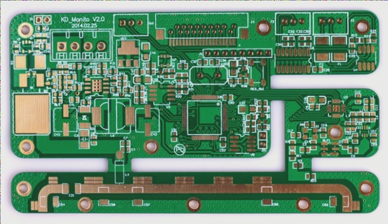
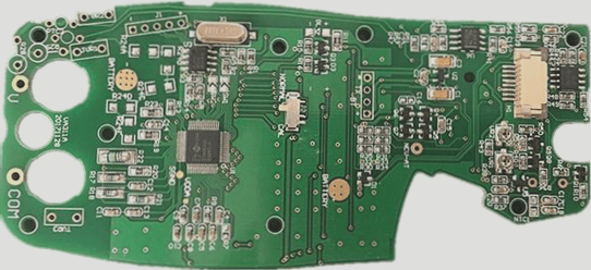
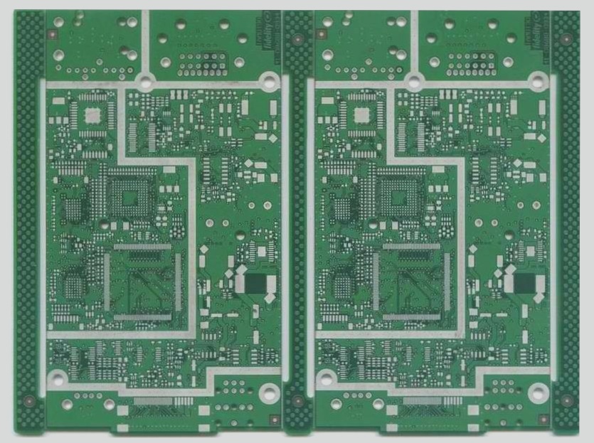
Layout is one of the most fundamental skills of a PCB design engineer. The quality of the wiring directly impacts the system’s performance. Most high-speed design theories are validated through layout. It is evident that wiring plays a crucial role in high-speed PCB design. This article will analyze the rationality of encountered situations in actual wiring and provide optimized routing strategies, focusing on three aspects: right-angle wiring, differential wiring, and serpentine line.
1. Right-Angle Routing
Right-angle wiring should be avoided in PCB wiring as much as possible, as it is a standard measure of wiring quality. How does right-angle wiring affect signal transmission? Right-angle wiring causes impedance discontinuity due to changes in line width, affecting signal transmission in three main ways: introducing capacitive loads that slow down rise time, causing signal reflection due to impedance discontinuity, and generating electromagnetic interference (EMI).
The equivalent capacitance of a right angle in a transmission line can be calculated using the empirical formula C=61W(εr)1/2/Z0. For a 4Mils 50-ohm transmission line (εr=4.3), the capacitance from a right angle is approximately 0.0101pF, leading to a rise time change of 0.556ps. The impedance decrease with increased line width due to right-angle routing results in signal reflection. While impedance changes caused by right-angle wiring range from 7%-20%, the maximum reflection coefficient is around 0.1. The impedance changes rapidly, within 10ps, minimally affecting signal transmission.
Despite common beliefs, right-angle traces do not significantly increase EMI compared to straight lines based on actual test results. The limited accuracy of current testing instruments may contribute to this perception. In general, right-angle routing’s effects are minimal, especially below GHz frequencies. Engineers should focus on layout, power/ground design, wiring design, and via holes. While right-angle wiring’s impact is minor, attention to detail remains crucial as signal frequencies increase, especially in RF design above 10GHz.
2. Differential Routing
Differential signals are increasingly utilized in high-speed circuit design, offering critical advantages. These signals consist of equal and inverted signals sent from the driving end, with the receiving end determining logic state based on voltage differences. Differential traces carry these signals and provide significant benefits over single-ended signal traces, including strong immunity to interference, effective EMI suppression, and accurate timing positioning. Differential signals’ exceptional characteristics make them ideal for high-speed circuits.


