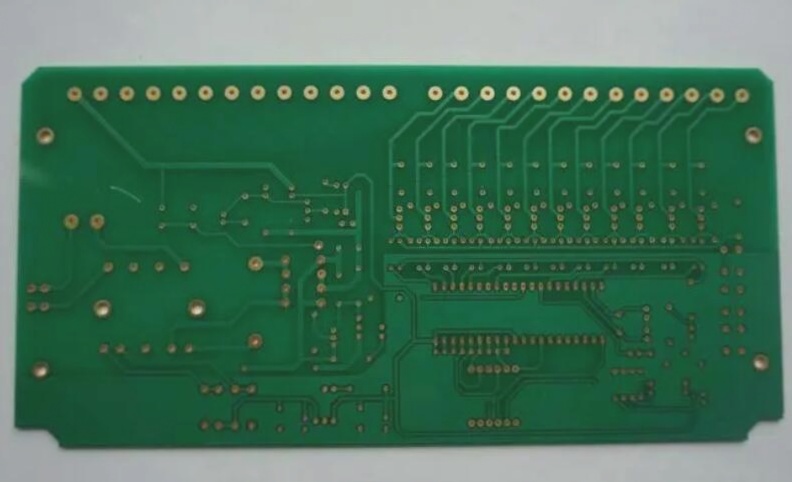
Exploring New Options for PCB Circuit Configuration
When working on a new PCB design, I wanted to experiment with different ways of configuring circuits on the board. Instead of using traditional 0R resistors, I had the idea to create surface solderable links that are designed to be either Normally Open (NO) or Normally Closed (NC), with the only difference being in the paste screen.
In the past, I’ve used cuttable link components with PCB traces, but I found them challenging to work with, especially at 0603 size. Additionally, once NC connections are made, they are permanent for that version of the PCB. My current approach involves using 0R 0402 parts for links, which works fine but I wanted to explore new possibilities.
To experiment, I designed a smaller footprint than a standard 0402, removed the soldermask over the entire part area, and placed the pads close together with a 0.15mm (6 mil) copper gap, which aligns with the minimum gap requirement of the board.
The NO version features solder directly over the pads, while the NC version has solder bridging across both pads, similar to a regular SOT23 pad in terms of paste volume.
While I’m uncertain if this approach will be successful due to the solder volume during reflow, I’m open to feedback and suggestions. If it doesn’t work as intended, I anticipate some minor adjustments needed for the prototypes. I welcome any advice on whether to revert to 0402 links or how to enhance this method for efficient circuit reconfiguration in a compact space.


