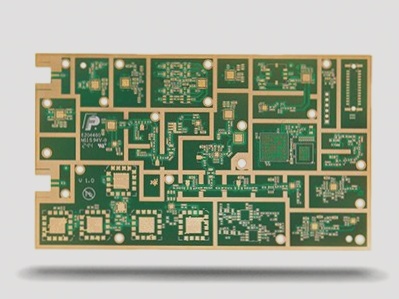
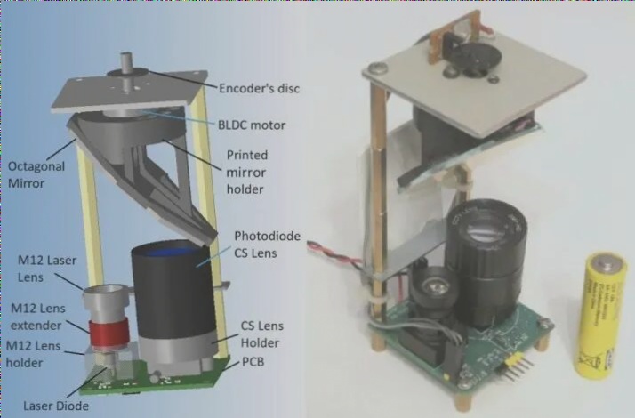
Santa Cruz, California—A startup founded by researchers from Carnegie Mellon University (CMU) is preparing CircuitSpace, a printed circuit board “synthesis” tool that claims to be the first to incorporate user-assisted automation components in PCB design tools. According to DesignAdvance Systems, this innovation could potentially cut PCB design time by up to 50%.
DesignAdvance, based in Pittsburgh, Pennsylvania, has announced an alpha test program involving four partners and plans to debut CircuitSpace at the PCB Design Conference on March 7, 2005. Their partners include Compunetix Inc., EMA Design Automation, Laurel Networks, and Marconi Corp.
CircuitSpace empowers designers to define constraints, perform design rule checking (DRC) and electrical rule checking (ERC). It features automatic and interactive constraint-driven component placement, automatic allocation of bypass capacitors, duplication of channels or ports, automatic clustering of critical components and associated circuits, and facilitates design reuse through module libraries.
The optimization algorithm within CircuitSpace can accommodate various constraints such as signal propagation delay, fixed component relationships, component orientation and symmetry, component height, thermal limits, manufacturability, and electrical requirements.
In developing CircuitSpace, DesignAdvance leveraged two patented platform technologies from CMU, encompassing a total of five patents. The company secured US$2.4 million in research funding from entities including the National Science Foundation, United Technologies, General Motors, Ford, and DaimlerChrysler.
Randy Eager, CEO and co-founder of DesignAdvance, obtained a license through CMU’s Technology Transfer Office. Previously, he held positions at BASF and the electronic packaging startup TriTech Group, and has five years of experience as a management consultant.
The technology behind DesignAdvance was pioneered by co-founders and chief scientists Jay McCormack and Chandan Aladahalli, both recent PhD graduates from CMU. Co-founder and chief technologist Jonathan Cagan is a professor of mechanical engineering at CMU.
—
Regarding your query about reversing the schematic diagram of the PCB board, could you clarify if you’re asking about reversing the layout or the orientation of components in the schematic itself?
 In the research of PCB reverse engineering, reverse engineering schematic refers to deriving PCB document diagrams or directly drawing PCB circuit diagrams based on actual products, aiming to explain the principles and working conditions of PCB boards. In addition, this circuit diagram is also used to analyze the functional characteristics of the product itself. In forward design, product development typically requires first conducting schematic design, followed by PCB design based on the schematic.
 Whether used in reverse engineering to analyze circuit board principles and product operating characteristics, or as the basis for PCB design in forward design, PCB schematics have special significance. So, how to generate PCB schematics in reverse based on file diagrams or actual objects, and what details need to be paid attention to during the reverse calculation process?
1. Reasonably divide functional areas
Reasonable division of functional areas can help engineers reduce unnecessary troubles and improve drawing efficiency when reverse designing a good PCB circuit board schematic. Generally speaking, components with the same function on the PCB board are arranged in a centralized manner, and through functional division, there is a convenient and accurate basis for reversing the schematic diagram.
However, the division of this functional area is not arbitrary. It requires engineers to have a certain understanding of the relevant knowledge of electronic circuits. Firstly, identify the core components in a certain functional unit, and then based on the wiring connections, other components of the functional unit can be found along the way to form a functional division. The formation of functional areas is the basis for schematic drawing. In addition, don’t forget to cleverly utilize the serial numbers of components on the circuit board during this process, as they can help you divide functions more quickly.
2. Find suitable reference materials
This reference can also be said to be the main component PCB network city used in the initial schematic drawing stage. After determining the reference components, drawings can be made based on the pins of these reference parts to ensure the accuracy of the schematic to a greater extent.
For engineers, determining reference materials is not a very complex task. Usually, components that play a major role in the circuit can be selected as reference components. They are usually larger in size and have more pins, making them easier to draw. For example, integrated circuits, transformers, transistors, etc. can all be used as suitable reference components.


