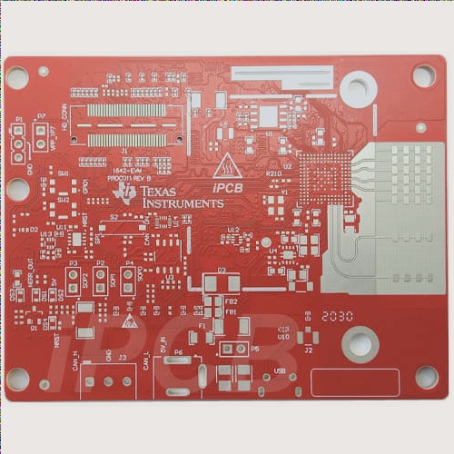
Millimeter wave radar sensors have the unique characteristic of operating in all weather conditions, making them a crucial component in automotive active safety systems (ADAS). The performance of millimeter wave radar sensors is influenced by various factors, with PCB circuit materials being particularly significant. To ensure high stability and consistent performance of millimeter wave sensors, it is essential to consider several key parameters in PCB circuit materials. This paper explores these parameters and their impact on the stability and consistency of automotive millimeter wave radar sensors. By analyzing how these parameters affect sensor performance, it aims to facilitate better selection of circuit materials suited for automotive millimeter wave radar applications.

With the rapid development of electronic technology, radar PCB technology has also made considerable progress. Radar was originally developed for military purposes. In the era of peace and development, radar technology is increasingly being transferred to civilian use. For example, the speed detection radar commonly used in traffic in our country, and the rapidly developing car collision avoidance radar, etc. As the cost continues to decrease, radar will be utilized more extensively in civil applications. Unlike laser ranging, radar ranging is not restricted by climatic conditions, offering long distance capability and high accuracy. Various radars may have different specific uses and structures, but they all share basic components including transmitters, transmitting antennas, receivers, receiving antennas, processing units, and displays. Other auxiliary equipment such as power supply units, data acquisition equipment, and anti-interference equipment are also included. One key advantage of radar is its ability to detect distant targets day and night, without being obstructed by fog, clouds, or rain. It boasts all-weather capabilities and has some penetration ability as well. As a result, radar has become essential not only in military affairs but also in various social and economic applications (such as weather forecasting, resource detection, environmental monitoring, etc.) and scientific research (celestial body research, atmospheric physics, ionospheric structure research, etc.). Synthetic aperture radars aboard satellites and aircraft have become crucial sensors in remote sensing. Ground-targeting radars can accurately detect ground shapes, with spatial resolutions ranging from several meters to tens of meters, independent of distance. Radar has also shown promising applications in flood monitoring, sea ice monitoring, soil moisture surveys, forest resource inventories, geological surveys, etc.
The linearity of radar waveforms is similar to other radar technologies. Automotive radars rely on receiving reflected signals from target objects, then analyze the correlations between the received signal and the original transmission signal in time, frequency, and phase to determine the relative speed and spatial position between the target object and the radar. One core technology of automotive radar is radar waveform design. Linear frequency modulated continuous wave (LFMCW, often referred to as FMCW) is a common radar waveform. The stability and linearity of the transmitted signal directly impact the radar’s ability to identify target objects. Since most automotive radars operate in the millimeter wave band, the inherent nonlinear characteristics of selected materials and components affect the final transmission and reception signals, requiring signal analysis algorithms to address jamming signals. Automotive radar uses the frequency and phase differences between transmitted and received signals to determine the speed and position of multiple target objects. Poor linearity in the radar system, especially the transmitter, can lead to ambiguous calculation results, causing major errors in target identification. For future automated driving control technology, minimizing error rates is crucial. Improving the linearity of the transmitted signal and ensuring product stability through accurate measurements are essential. Linearity measurements are typically performed using high-end instruments to reduce errors. Current high-end instruments can analyze signals with bandwidths exceeding 1 GHz to ensure accurate radar signal measurement.
Automobile millimeter wave radar is expanding rapidly, providing enhanced driving aids and increased vehicle safety. Phased arrays are commonly used for both transmitting and receiving antennas in automotive radar applications. Linear or planar arrays are employed based on design needs. While main parameters of array antennas can be calculated using mathematical formulas, the calculation results are valid only under certain conditions where mutual coupling effects between array elements can be ignored. Increasing the relative distance between array elements can help meet these conditions but may lead to larger end products. In cases where precise array element design cannot be achieved through calculation, measurements become essential in the optimization process, supported by computer software for data analysis. Array antenna optimization typically involves the following steps:
1) Designing radiation field patterns for basic array elements
2) Evaluating mutual coupling between array elements
3) Designing radiation field patterns for the antenna array
4) Designing the array feeding system
5) Integrated design of the millimeter wave radar transceiver system
6) Considering the impact of vehicle bumpers.

