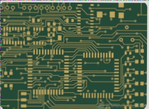
1. **PCB Size Specifications**
– This includes the dimensions of the circuit board, as well as acceptable deviations from the specified size.
– Board thickness, including any allowable thickness variations, must also be within specified limits.
– Perpendicularity of the board and its edges is crucial, and any deviation from the perpendicularity tolerance is considered non-compliant.
– Warpage should be minimized and kept within predefined limits to ensure the board’s reliability during assembly and operation.
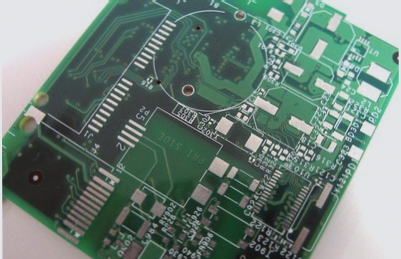
2. **Appearance Criteria**
– The PCB must be free from defects such as cracks, scratches, burrs, and delamination.
– The aluminum oxide film, if present, should meet quality standards, ensuring that it does not affect the electrical or mechanical properties of the board.
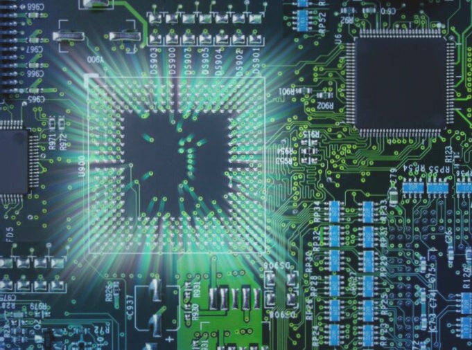
3. **Performance Specifications**
– **Peel Strength**: The adhesive bond strength between layers or between the copper traces and substrate must meet a minimum threshold to ensure mechanical integrity.
– **Surface Resistivity**: The resistivity of the surface must be measured to ensure it does not interfere with signal integrity and electrical performance.
– **Minimum Breakdown Voltage**: The PCB must withstand high voltages without electrical breakdown, ensuring safety in high-voltage applications.
– **Dielectric Constant**: This value must fall within the specified range to ensure consistent signal transmission and minimize signal distortion.
– **Flammability**: The PCB material should comply with fire safety standards, ensuring it does not catch fire under normal operating conditions.
– **Heat Resistance**: The PCB must tolerate high temperatures without degradation, maintaining its structural and electrical properties in elevated temperature environments.
### Measurement Methods
1. **Dielectric Constant and Dielectric Loss Factor**
– These properties are typically measured using a variable Q series resonance method. This technique involves connecting the sample to a high-frequency circuit in series with a tuning capacitor. The Q value of the series circuit is then measured, from which the dielectric constant and loss factor can be calculated. This method provides accurate and reliable data for the board’s electrical performance.
2. **Thermal Resistance Measurement**
– Thermal resistance is determined by calculating the ratio of the temperature difference between two points on the PCB to the thermal conductivity of the material. This measurement is critical for understanding how well the PCB can dissipate heat and withstand temperature variations during operation.
By adhering to these technical requirements and measurement methods, PCBs can be produced with high reliability, ensuring their performance in a wide range of electronic applications.
### Aluminum PCB Manufacturing Process: Key Insights and Best Practices
#### 1. Machining and Punching Challenges
Aluminum PCBs are known for their durability and thermal management, but they present certain challenges during the manufacturing process, especially when it comes to machining and punching.
– **Drilling and Burrs**: Drilling aluminum substrates requires precision, as burrs along the edges of the holes can significantly affect the quality of the pressure test. Burrs can compromise the performance of the circuit board by interfering with the soldering process or creating weak points.
– **Punching and Molding**: The punching process for aluminum substrates demands advanced molds. These molds are critical to achieving accurate shapes and clean edges. After punching, it’s crucial that the edges are free of burrs to avoid damage to the solder mask and ensure a high-quality finish. Military-grade models are often used for punching, ensuring precise hole placement and minimal stress on the board. The punch force is typically an upper shear drop to avoid warping, with an acceptable warpage limit of 0.5%.
#### 2. Surface Protection and Handling
Aluminum substrates are sensitive to environmental factors and improper handling, which can degrade the surface and affect the board’s functionality.
– **Avoiding Surface Damage**: Contact with the aluminum base surface must be avoided at all costs during the production process. Any physical touch or exposure to certain chemicals can discolor or oxidize the surface, making it unacceptable for high-quality applications. The surface may require repolishing if damaged, but this is to be avoided at all costs.
– **Passivation and Protective Films**: To prevent surface damage, some manufacturers apply passivation technology, while others use protective films during key steps, such as before and after the Hot Air Solder Leveling (HASL) process. Protective coatings or films are critical in maintaining the integrity of the aluminum surface and ensuring the final product meets stringent quality standards.
#### 3. High Voltage Testing
Aluminum PCBs used in communication power supplies require stringent testing, particularly high-voltage tests to ensure safety and reliability.
– **Overvoltage Testing**: All aluminum PCBs undergo a 100% high-voltage test. Depending on customer requirements, either DC or AC power is applied, with voltages typically ranging between 1500V and 1600V. The testing duration varies from 5 to 10 seconds, depending on the specific application.
– **Potential Issues**: During the overvoltage test, any contamination, holes, or burrs on the aluminum surface can lead to electrical failures, such as leaks or fires. The presence of even slight insulation on the board surface can cause test failures. The pressure test may involve foamed layers and discharge mechanisms to simulate real-world conditions, further emphasizing the need for a pristine surface during manufacturing.
#### 4. 
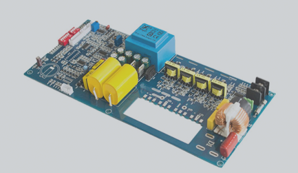
Aluminum PCB Manufacturing Specifications
– **Copper Thickness**: Aluminum PCBs are typically used for high-power applications where thermal management is essential. This necessitates the use of thicker copper foil, often 3 ounces or more. However, when using thicker copper foil, engineering compensation for line width is required during the etching process. Without this adjustment, the etched copper traces may be too wide, potentially affecting the functionality of the PCB.
– **Protective Films and Chemical Sensitivity**: Before processing the aluminum base, it is crucial to apply a protective film. This film safeguards the aluminum surface from chemical corrosion, which could result in appearance damage or performance degradation. The protective film must remain intact throughout the production process to ensure consistent results. Additionally, care must be taken to avoid scratches or gaps that could compromise the integrity of the film.
#### 5. Milling and Cutting Considerations
– **Milling Process**: Milling aluminum substrates presents unique challenges compared to fiberglass-based PCBs. The milling cutters used for fiberglass boards are softer and faster, while those designed for aluminum substrates are harder and slower. The speed of production when milling aluminum substrates is typically two-thirds slower than that of fiberglass boards due to the higher hardness of the material.
– **Heat Management**: The milling process for fiberglass boards primarily relies on the heat dissipation system of the machine. In contrast, aluminum substrates require additional heating during processing to manage the heat generated during cutting and milling. Without proper temperature control, the aluminum can deform, compromising the overall quality of the PCB.
### Conclusion
Aluminum PCB manufacturing requires a careful balance of precision, material handling, and quality control to ensure optimal performance. Key considerations include the avoidance of surface damage, rigorous testing protocols, and careful milling practices to manage the unique properties of aluminum substrates. By adhering to these best practices, manufacturers can ensure the production of high-quality, reliable aluminum PCBs for demanding applications.