An obstacle detection unit is a crucial component in various applications, such as robotics and security systems. Infrared (IR) sensors are commonly used for these purposes. A common issue with certain circuit designs is that the detection units can be sensitive to ambient light, leading to unstable or noisy performance.
In this project, we have selected a suitable IR receiving component and designed the circuit to operate as stably as possible. Additionally, the sensor’s sensitivity can be adjusted to detect obstacles at varying distances.
Refer to Figure 1 for the schematic diagram. The widely used 555 timer IC generates a 38kHz square wave, which can be adjusted by the R5 potentiometer. The receiver uses the TSOP1738 (HS0038) IR receiver module, which is sensitive to the 38kHz IR pulse and activates its output accordingly.

Figure 1: Schematic diagram of the IR obstacle detector
According to the TSOP1738 datasheet: “The TSOP17XX series are miniaturized receivers for infrared remote control systems. The PIN diode and preamplifier are assembled on a lead frame, and the epoxy package is designed with an IR filter. The demodulated output signal can be directly decoded by a microprocessor. TSOP17XX is the standard IR remote control receiver series, supporting all major transmission codes.”
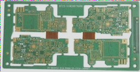
The features of the TSOP1738, particularly its embedded IR filter, make it well-suited for this application. Figure 2 illustrates the PCB design for the circuit. The PCB is primarily designed using surface-mount devices (SMD), resulting in a compact 3.2cm x 1.8cm board size.

Figure 2: PCB board design of the IR obstacle detection circuit
As seen in the PCB silkscreen, an isolation barrier must be placed between the IR diode and the receiver. These two components are positioned next to each other, so it is important to ensure that the receiver only responds to the IR light reflected from the front.
If no suitable material is available for the barrier, you can cover the 5mm IR diode with black heat shrink tubing, ensuring that the light exits only from the front.
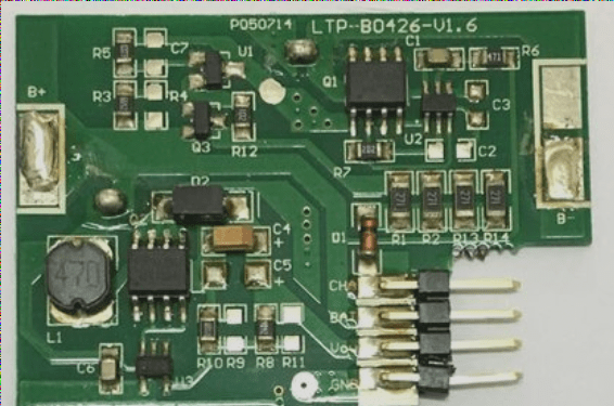
Figure 3 provides a 3D view of the assembled PCB, allowing you to inspect the installed components.

Figure 3: 3D view of the assembled PCB
The LED D3 indicates the correct power connection, while LED D1 lights up when an obstacle is detected within the sensor’s range.
The R1 potentiometer controls the transmission power, which, in turn, affects the detection range. The R5 potentiometer adjusts the frequency. If you have an oscilloscope, you should be able to observe a signal like the one shown in Figure 4 at pin-3 of U1 (the output). Adjust R5 to achieve a 38kHz signal. The R5 potentiometer allows you to accommodate a wide range of IR receivers that may operate at different frequencies.

Figure 4: 38kHz signal at the 555 timer’s pin-3
A 3-pin male header connects the board to an external circuit. Connect the +5V supply to the positive terminal and the ground to the negative terminal. The “S” output acts as an active low trigger. This means that when the sensor detects an object, the “S” output will connect to ground, causing LED D3 to light up. The SMD components used are in the 0805 package.
If you have any questions about PCBs or PCBA, feel free to contact me at info@wellcircuits.com.