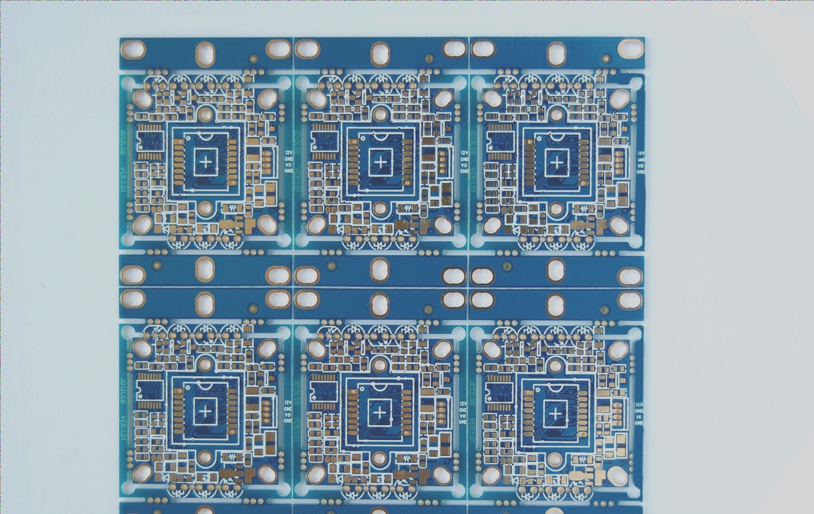
For electronic devices, a certain amount of heat will be generated during operation, causing the internal temperature of the device to rise rapidly. If the heat is not dissipated in time, the device will continue to heat up, leading to overheating and a drop in performance. Therefore, it is crucial to implement effective heat dissipation treatments for PCB boards. Heat dissipation in PCB circuit boards is a critical aspect, so let’s discuss some heat dissipation techniques for PCB circuit boards.

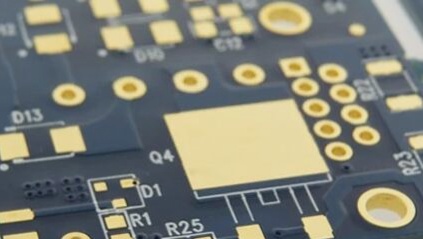
1. Heat dissipation through the PCB itself: The commonly used PCB sheets are copper clad/epoxy glass cloth substrates, phenolic resin glass cloth substrates, and some paper-based copper clad sheets. While these substrates offer excellent electrical and processing properties, they have poor heat dissipation capabilities. It is challenging for heat to be conducted through the PCB resin itself; instead, heat needs to be dissipated from the component surface to the surrounding air. With the miniaturization and high-density installation of electronic products, relying solely on the component surface for heat dissipation is no longer sufficient. To address this, it is essential to enhance the heat dissipation capacity of the PCB itself, especially for areas in direct contact with heating elements. Adding heat-dissipating copper foil, utilizing large-area power supply ground copper foil thermal vias, and exposing copper on the back of ICs can help reduce thermal resistance and improve heat dissipation.

2. Placement Strategies:

1) Place thermally sensitive devices in areas with cold air flow.

2) Position temperature detection devices in the hottest spots.

3) Arrange devices based on their heat generation and dissipation capabilities. Devices with low heat output or poor heat resistance should be placed at the cooling airflow inlet, while devices with high heat generation should be located at the airflow outlet.

4) Place high-power devices closer to the edge of the PCB horizontally and towards the top vertically to minimize the impact on other devices’ temperature.

5) Optimize airflow paths by avoiding large airspaces and ensuring components are configured to reduce resistance.

6) Sensitive temperature devices should be placed in cooler areas and staggered horizontally to avoid direct heat exposure.

7) Locate high-power and high-heat devices near optimal heat dissipation locations, avoiding corners and edges unless heat sinks are used.

8) Avoid hotspots by distributing power evenly throughout the PCB to maintain consistent temperature performance.

3. Adding Radiators and Heat-conducting Plates: For PCBs with a few high-heat-generating devices, radiators or heat-conducting pipes can be added. For larger numbers of heating devices, a heat dissipation cover or a flat radiator can be installed to enhance cooling efficiency.

4. Design Considerations:

– Use routing designs that maximize copper foil utilization and incorporate thermal holes for improved heat dissipation.

– Maintain consistent thermal performance by analyzing the thermal efficiency of printed circuits and avoiding hotspots that could affect overall circuit operation.

By implementing these heat dissipation strategies in PCB design, it is possible to enhance the reliability and performance of electronic devices by effectively managing internal temperatures.

Leave a Comment

Contact

WellCircuits
More than PCB

Upload your GerberFile(7z,rar,zip)